
Entertainment induction cooker

A technology of induction cooker and electromagnetic wire, which is applied in the field of induction cooker and can solve the problems of consumers being unattractive and unable to provide interesting functions

Inactive Publication Date: 2020-05-12
朱小菊
View PDF0 Cites 2 Cited by
  • Summary
  • Abstract
  • Description
  • Claims
  • Application Information

AI Technical Summary

Problems solved by technology

With the rejuvenation of catering consumers, the demand for fun in the catering consumption process is becoming more and more prominent. For now, the induction cooker that can be configured in restaurants is very traditional, basically limited to heating functions, and cannot provide other fun. Sexual function, as far as the furnace body itself is concerned, is basically unattractive to consumers

Method used

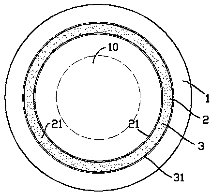
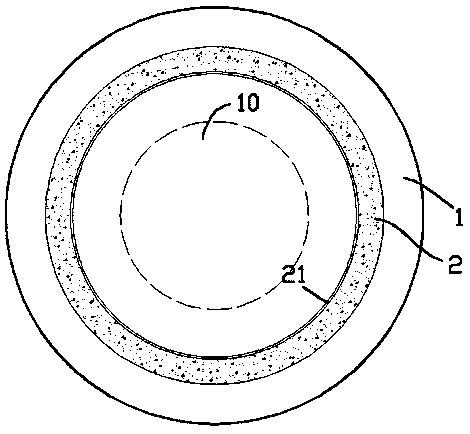
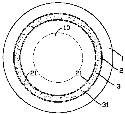

Image

  • Entertainment induction cooker
  • Entertainment induction cooker
  • Entertainment induction cooker

Examples


Embodiment 1

[0016] exist figure 1 In the shown embodiment 1, the electromagnetic induction cooker of the present invention includes a furnace body 1; an electromagnetic coil (not shown) coupled to the control module is provided in the center of the furnace body; the upper surface of the furnace body 1 is provided with a surrounding central heating The transparent annular sealing cavity 2 of the zone 10, a transparent annular elastic capsule 3 is embedded in the annular sealing cavity 2, and the annular elastic capsule 3 is filled with water body, and bright chips are suspended in the water body; the annular elastic capsule 3 The cross section should be circular, so that the water body in the annular elastic capsule 3 can form a convex lens magnification effect on the bright wafer, and in the extrusion-relaxation process of the annular elastic capsule 3, the magnification effect changes, so that the bright wafer has a visual dimension It also fluctuates periodically; the outer peripheral s...

Embodiment 2

[0020] exist figure 2 In the shown embodiment 2, the electromagnetic induction cooker of the present invention includes a furnace body 1; the center of the furnace body 1 is provided with an electromagnetic wire coil coupled to the control module; the upper surface of the furnace body 1 is provided with a transparent An annular sealed cavity 2 is filled with a conductive solution, and a bright wafer with a conductive surface is suspended in the conductive solution; an annular conductive layer 21 is formed on the inner peripheral surface of the annular sealed cavity 2 .

[0021] In the second embodiment, the conductive solution is a sodium chloride solution; the bright chip is composed of plastic fragments coated with metal powder on the surface, or aluminum foil fragments. The bottom of the transparent annular sealed chamber 2 is also provided with an illuminating part, which can form the light passing through the transparent annular sealed chamber 2 from the bottom of the tr...


PUM


Abstract

The invention relates to an entertainment induction cooker. The entertainment induction cooker comprises a cooker body, and an electromagnetic wire coil coupled to a control module is arranged in thecenter of the interior of the cooker body; a transparent annular sealing cavity surrounding a central heating area is formed in the upper surface of the cooker body, a transparent annular elastic bagis embedded in the annular sealing cavity, the annular elastic bag is filled with a water body, and bright wafers are suspended in the water body; and a circle of annular conducting layer is arrangedon the outer circumferential face of the annular elastic bag, and a circle of annular conducting layer is also arranged on the inner circumferential face of the annular sealing cavity. In the heatingprocess of the induction cooker, the dynamic artistic effect can be shown, high interestingness and ornamental value are achieved, and meanwhile electromagnetic radiation can be restrained to a certain extent.

Description

technical field [0001] The invention relates to the field of catering equipment, in particular, it is an electromagnetic cooker. Background technique [0002] The induction cooker has the advantages of fast heating speed, high economical practicability, safety and no open flame, etc., and is loved by consumers. The principle of the induction cooker is the phenomenon of electromagnetic induction, which uses the alternating magnetic field generated by the excitation coil to cause eddy currents to appear inside the pot in the alternating magnetic field, thereby heating the food in the pot. [0003] Due to the above advantages, the induction cooker not only has a good market in the household, but also has obtained huge popularity in the field of catering business. With the rejuvenation of catering consumers, the demand for fun in the catering consumption process is becoming more and more prominent. For now, the induction cooker that can be configured in restaurants is very trad...

Claims


Application Information

Patent Timeline
IPC IPC(8): F24C7/06H05B6/12F21V3/02F21V7/04F21V33/00
CPCF21V3/02F21V7/04F21V33/0044F24C7/062H05B6/1218
Inventor 朱小菊
Owner 朱小菊
Learn More