
Tomosynthesis with shifting focal spot and oscillating collimator blades

a collimator blade and focal spot technology, applied in the direction of instruments, diaphragms/collimeters, diaphragms for radiation diagnostics, etc., can solve the problems of reducing image quality, image blurring, and moving x-ray sources

Active Publication Date: 2011-08-04
HOLOGIC INC
View PDF40 Cites 30 Cited by
  • Summary
  • Abstract
  • Description
  • Claims
  • Application Information

AI Technical Summary

Problems solved by technology

However, movement of the x-ray source introduces some technological complications.
Typical tomosynthesis systems are arranged to smoothly and continuously traverse a path during an image scan because stop-and-start scanning procedures tend to reduce image quality.
The resultant focal spot movement causes image blurring and reduces diagnostic accuracy.

Method used


Image

  • Tomosynthesis with shifting focal spot and oscillating collimator blades
  • Tomosynthesis with shifting focal spot and oscillating collimator blades
  • Tomosynthesis with shifting focal spot and oscillating collimator blades

Examples


Embodiment Construction

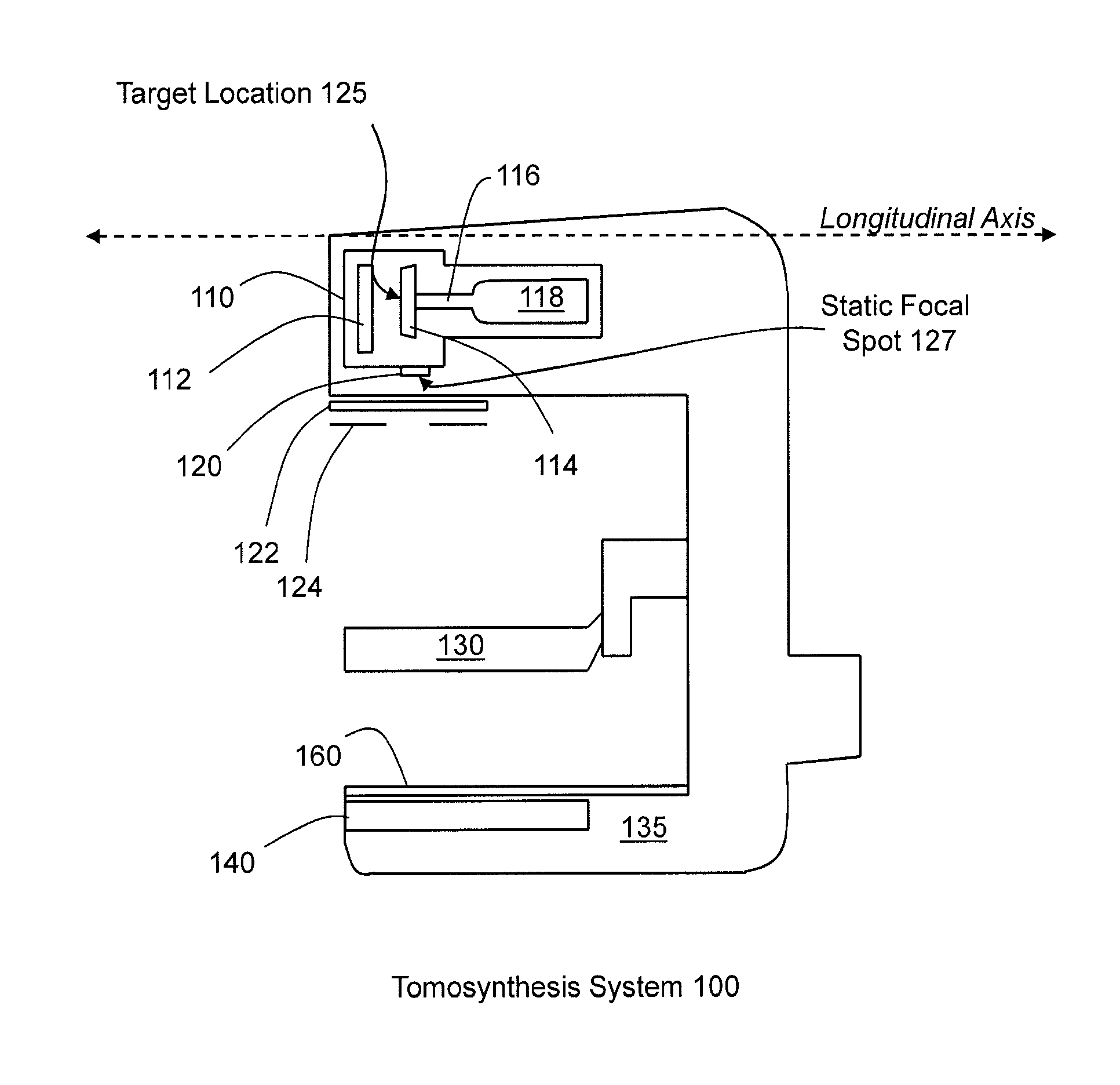
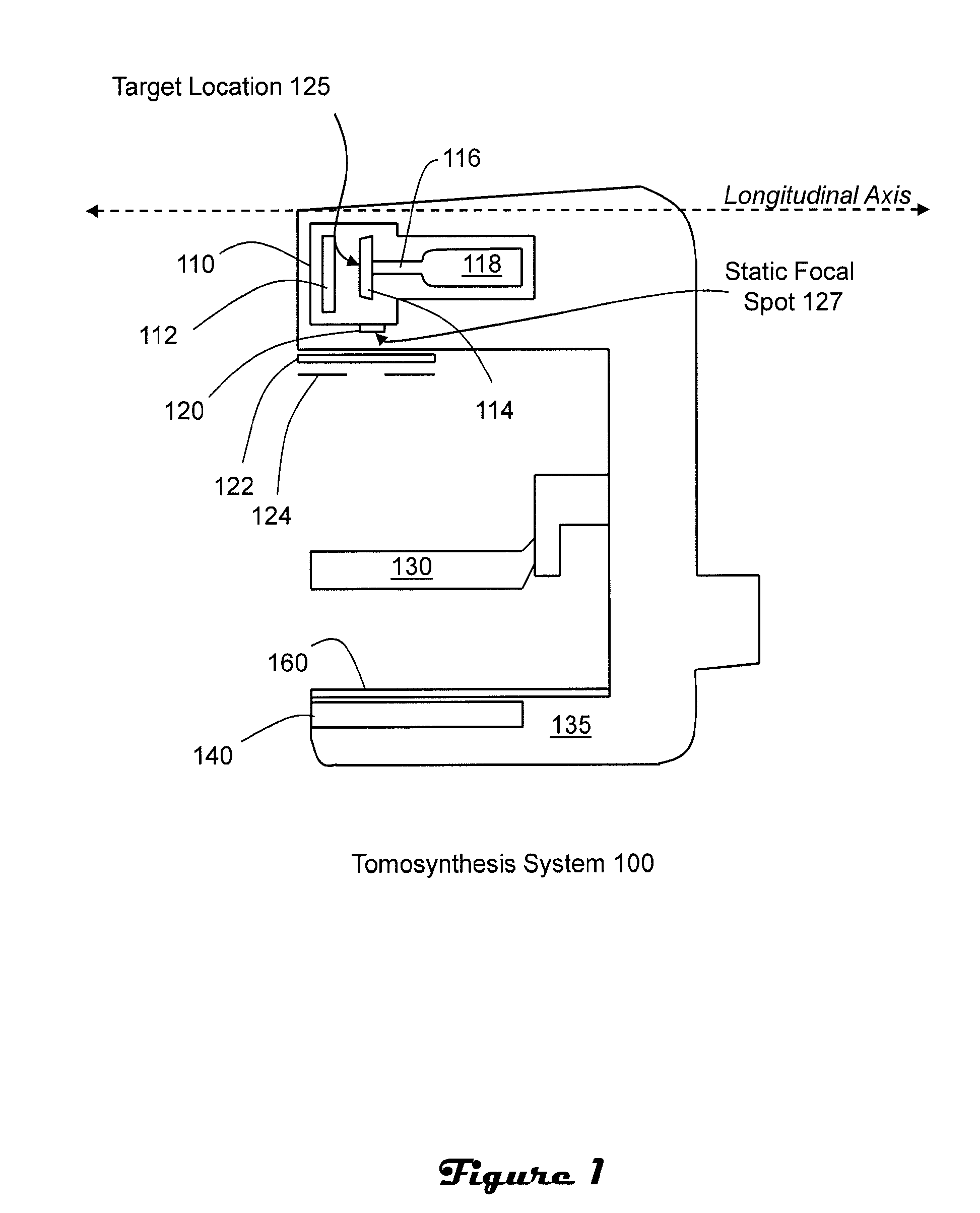
[0010]FIG. 1 illustrates a tomosynthesis system 100 which includes an x-ray tube 110, upper and lower compression paddles 130, 135, an anti-scatter grid 140 and a detector 160. The x-ray tube 110 includes a cathode 112, an anode 114 that is mounted on a shaft 116 and rotated by a motor 118, and a tube port 120. Also shown attached to the x-ray tube are a filter 122 and collimating means such as collimator blades 124.

[0011]The illustrated x-ray tube is a glass vacuum tube. Within the cathode 112 is a heated filament. When the x-ray tube is turned ‘on,’ a current is passed through the filament, thereby heating the filament and causing high energy electrons to be dislodged from the filament. A high voltage between cathode and anode causes the electrons to accelerate toward a target location 125 on the anode. The anode is made, for example, from tungsten and is rotated by motor 118 to avoid local overheating of the target location 125 on the anode. Electrons are focused to a specific ta...


PUM


Abstract

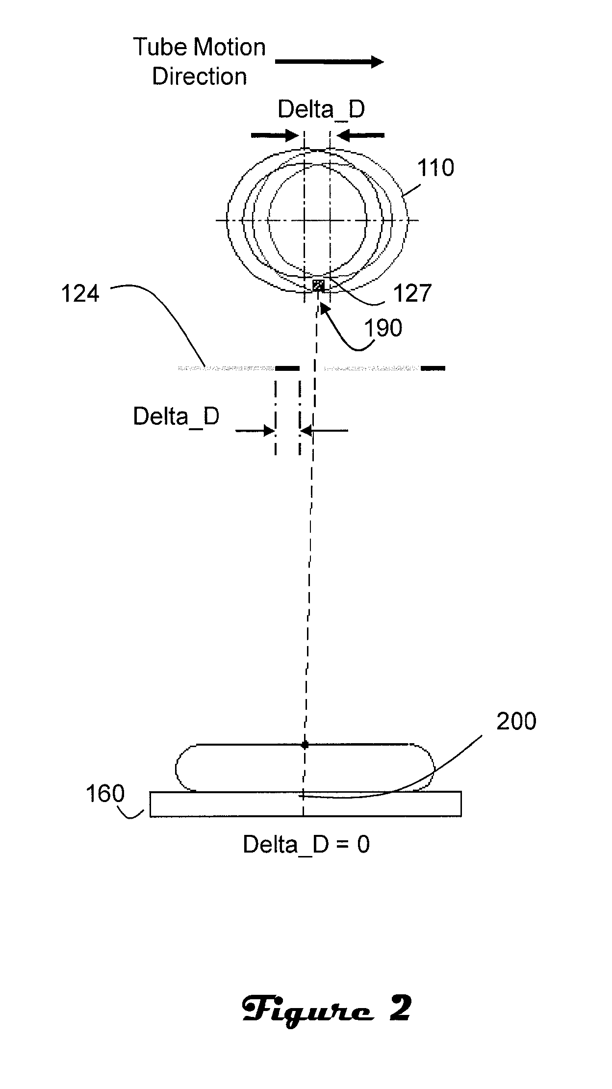
In a tomosynthesis system a static focal spot is moved in a direction opposite to and generally synchronized with the directional movement of an x-ray source and X-ray collimator blades are moved during each exposure in synchronization with the shifting of the static focal spot. The synchronized movement of the static focal spot, x-ray tube and collimator blades helps keep the effective focal spot fixed in space relative to the breast, detector or both during the entire duration of the exposure and keeps the x-ray field on the detector and breast static. The shifting collimator blades follow an oscillating pattern over the multiple x-ray exposures of a tomosynthesis scan.

Description

CROSS-REFERENCE TO RELATED APPLICATIONS[0001]This application is a continuation-in-part of U.S. patent application Ser. No. 12 / 623,472 filed Nov. 23, 2009, which claims priority to U.S. Patent Provisional Application Ser. No. 61 / 117,453 filed Nov. 24, 2008.BACKGROUND OF THE INVENTION[0002]Breast tomosynthesis is a three-dimensional imaging technology in which images of a stationary compressed breast are acquired at multiple angles during a short scan. The images are organized as a series of thin high-resolution slices that can be displayed individually or in a dynamic cine mode. Breast tomosynthesis systems are similar to mammography systems except that the x-ray source is moved to a variety of different imaging positions during image acquisition. Reconstructed tomosynthesis slices advantageously reduce or eliminate problems caused by tissue overlap and structure noise in single slice two-dimensional mammography imaging. Digital tomosynthesis, which combines digital image capture an...

Claims


Application Information

Patent Timeline
IPC IPC(8): A61B6/03G21K1/04
CPCA61B6/03G21K1/04A61B6/502A61B6/06A61B6/035A61B6/025A61B6/542G21K1/02
Inventor REN, BAORUISMITHFARBIZIO, TOMJING, ZHENXUESTEIN, JAY
Owner HOLOGIC INC
Learn More