System and method for object recognition based on three-dimensional adaptive feature detectors

Active Publication Date: 2011-08-04
TOYOTA JIDOSHA KK
View PDF35 Cites 11 Cited by
  • Summary
  • Abstract
  • Description
  • Claims
  • Application Information

AI Technical Summary

Benefits of technology

[0008]In order to address these problems among others, the present invention uses data from a 3D imaging device, such as a 3D laser scanner. Unlike traditional two-dimensional scanners, also known as line scanners, 3D imaging devices can provide highly accurate distance measurements in the spherical coordinate system.

Problems solved by technology

More importantly, the number of features can be very large, making the task of object recognition computationally very demanding.
Object recognition is known to be especially difficult if the object position and orientation is not constrained (i.e., the object may appear from an arbitrary viewing angle).
Also, reliable rotational invariant recognition of objects has remained an unsolved problem.
However, the system and method described therein, in some aspects, is computationally demanding and can benefit from more accurate recognition of objects.

Method used


Image

  • System and method for object recognition based on three-dimensional adaptive feature detectors
  • System and method for object recognition based on three-dimensional adaptive feature detectors
  • System and method for object recognition based on three-dimensional adaptive feature detectors

Examples


Embodiment Construction

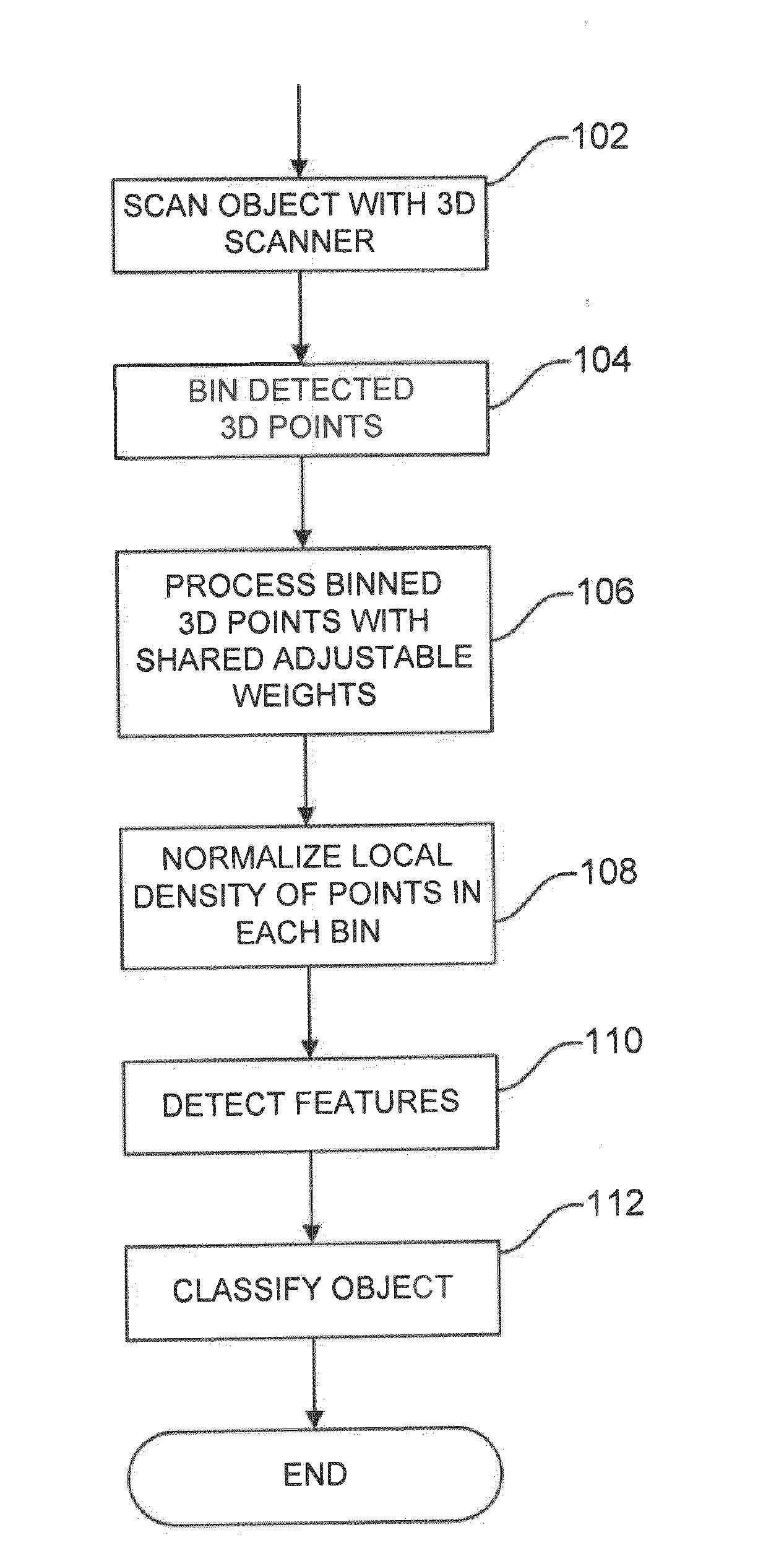
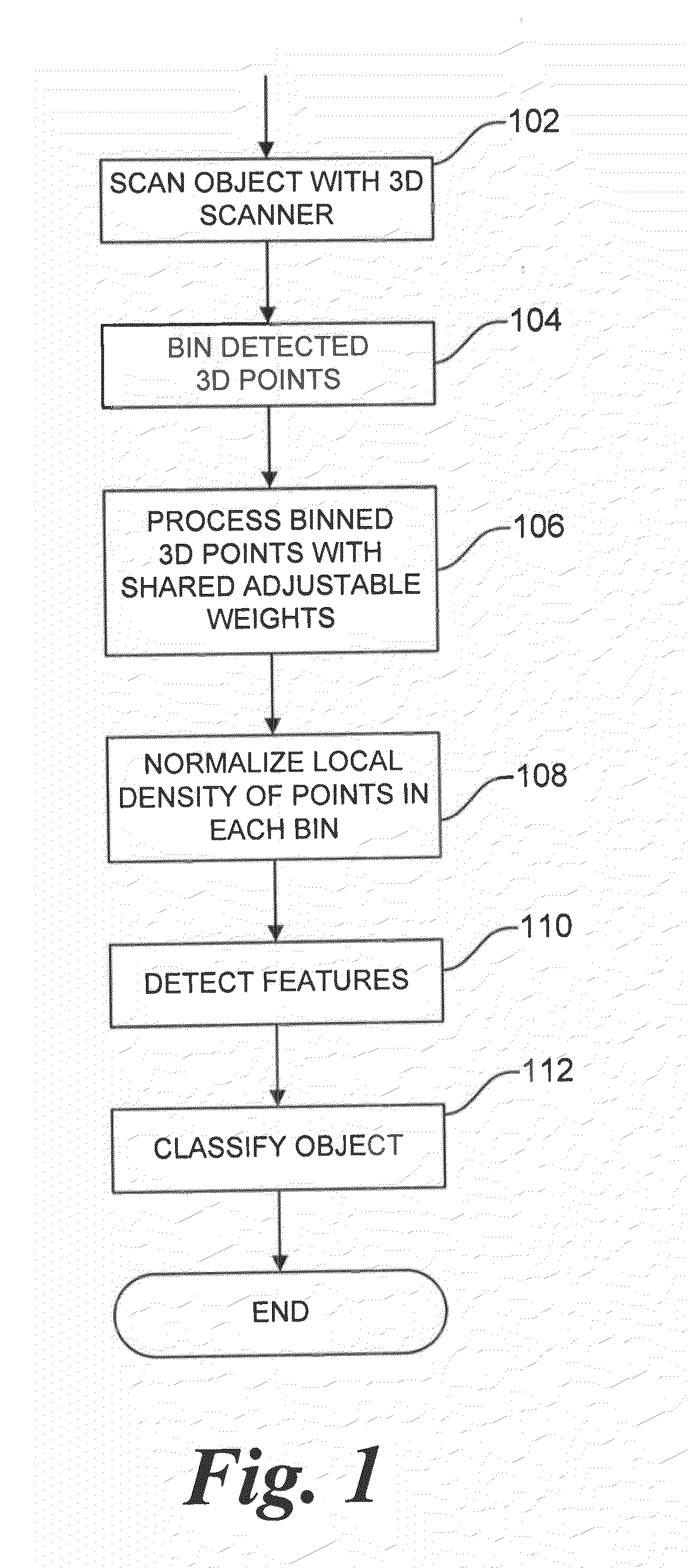
[0019]Referring now to the drawings, wherein like reference numerals designate identical or corresponding parts / steps throughout the several views. FIG. 1 is a flowchart illustrating steps for calculating an output of processing elements of a computational system according to one embodiment of this disclosure. In step 102, an object is scanned using a 3D scanner. Imaging of an object can be accomplished in three dimensions using both scanning and non-scanning systems. The invention is not limited to a scanning system, but a system providing highly accurate distance measurements is preferred, such as a scanning system employing a 3D laser. Preferably, the 3D laser design includes many laser sending-receiving heads rotating around a vertical axis.

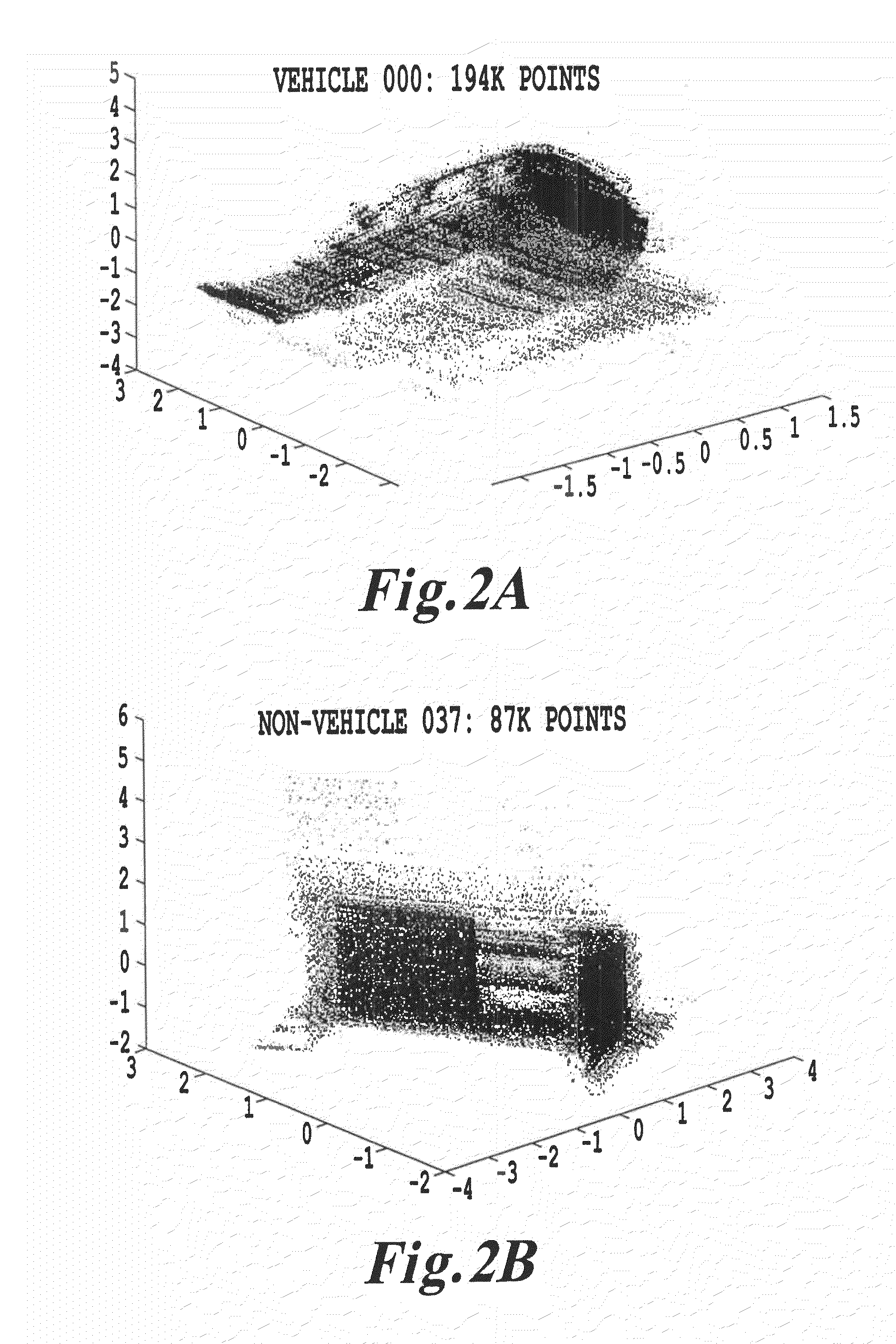
[0020]The data from a 3D scanner can be represented conveniently in three spatial dimensions: X coordinate, Y coordinate, and Z coordinate of the Cartesian coordinate system. However, the computational system of this disclosure can be adapted...


PUM


Abstract

Method and system for imaging an object in three-dimensions, binning data of the imaged object into three dimensional bins, determining a density value p of the data in each bin, and creating receptive fields of three dimensional feature maps, including processing elements O, each processing element O of a same feature map having a same adjustable parameter, weight Wc1. The density values p are processed with the processing elements O to determine an output value o for at least each three dimensional location of the imaging of the object having a density value p above a predetermined threshold value. An object is classified by processing the output values o with a committee of classifiers, and the classification of the object is communicated.

Description

BACKGROUND[0001]1. Field of Invention[0002]This disclosure relates generally to computerized object recognition and, more particularly, to object recognition and classification using a three-dimensional (3D) system.[0003]2. Discussion of the Background[0004]Computerized object recognition is the process of finding or identifying an object in an image or video. Recognizing an object can include the process of classifying objects belonging to distinct classes. Object classifying using computer vision can be applied to, among other things, automated production processes, security, and automotive applications.[0005]Typical current technology for object recognition uses images from a camera or another suitable sensor. Each image serves as an input to an object recognition algorithm, such as a neural network or another machine learning system. The image is usually fed into the algorithm as a collection of features, e.g., pixel intensities. The temporal order of such features is meaningles...

Claims


Application Information

Patent Timeline
IPC IPC(8): G06K9/00
CPCG06K9/00G06V10/7715
Inventor PROKHOROV, DANIL V.JAMES, MICHAEL R.
Owner TOYOTA JIDOSHA KK
Why Eureka
Try Eureka