Energy storage unit

Inactive Publication Date: 2011-08-04
SAMSUNG SDI CO LTD
View PDF12 Cites 16 Cited by
  • Summary
  • Abstract
  • Description
  • Claims
  • Application Information

AI Technical Summary

Benefits of technology

[0022]According to another embodiment, at least one hollow space, which is formed in the cooling body and through which a coolant is able to flow, is assigned to each of the cooling elements, wherein the hollow space in particular extends in parallel to the flat cells. In this way, the cooling capacity can be considerably increased. Depending on the respective embodiment, a separately fed hollow space can be assigned to each of the cooling elements or the individual hollow spaces can be interconnected such that eventually a continuous overall hollow space, which has, for example, a meandering shape, is obtained for the corresponding energy storage unit. The respective hollow space can also be formed by the fact that the cooling body has a depression or a recess covered in a fluid-tight manner by the connection unit.
[0023]The hollow space can have a U-shaped cross section having tw

Problems solved by technology

However, the cooling devices used conventionally for heat dissipation are expensive and require relati

Method used


Image

  • Energy storage unit
  • Energy storage unit
  • Energy storage unit

Examples


Example

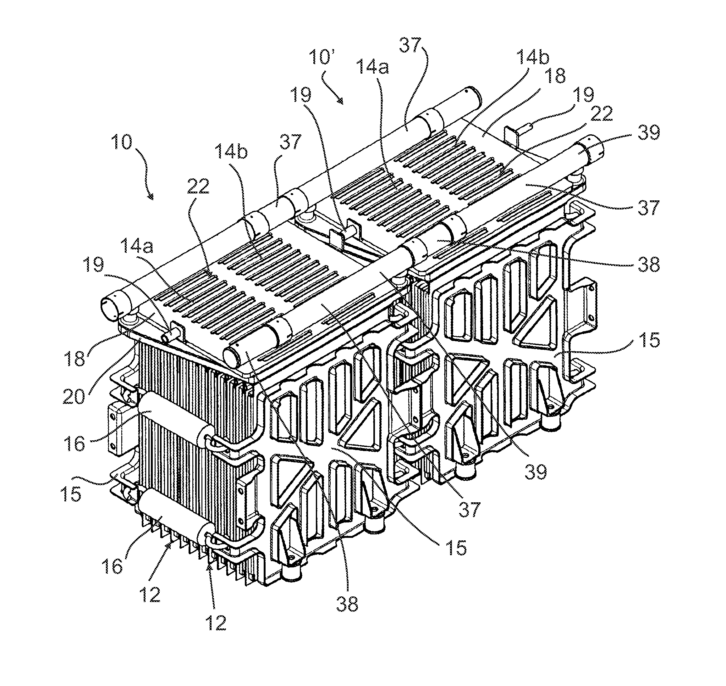
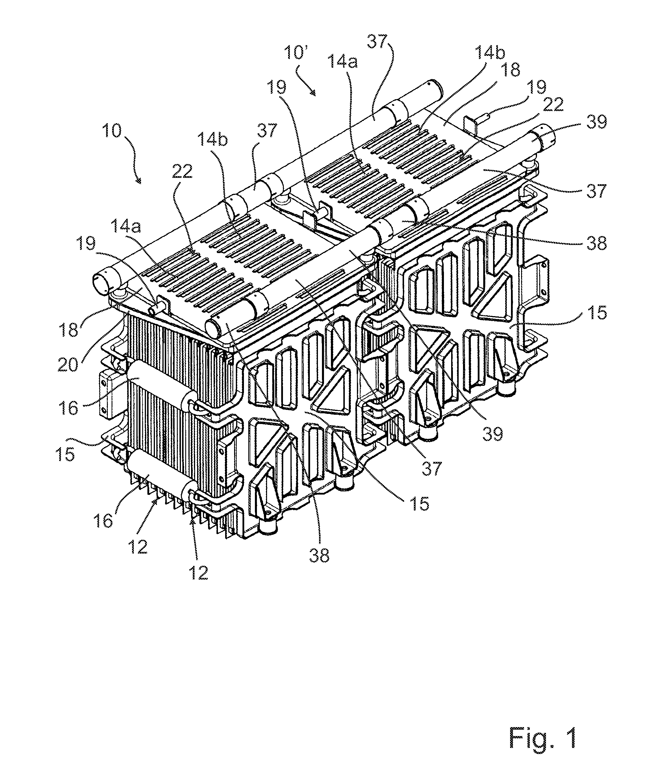
[0030]FIG. 1 shows a perspective view of two energy storage units 10, 10′. The two energy storage units 10, 10′ are joined together in order to form a superordinate unit. Within the framework of a modular concept, thus, depending on the application requirement, any number of energy storage units can be joined together in a line or be combined to form a two- or three-dimensional matrix in order to eventually constitute a vehicle battery, for example.

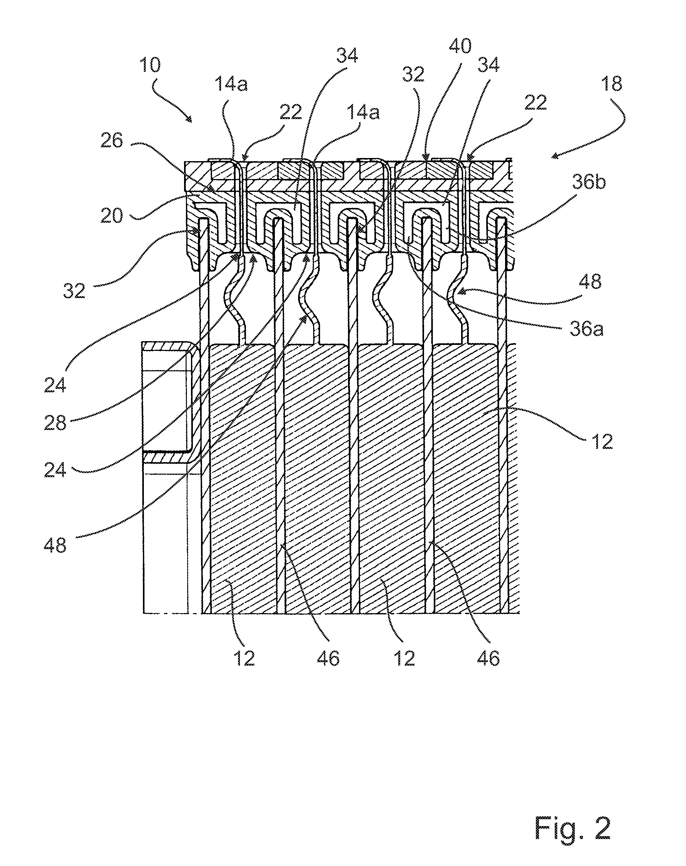
[0031]Each of the energy storage units 10, 10′ comprises a plurality of prismatic cells / flat cells 12 arranged in parallel to one another in a stack. The cells 12 can, for example, be lithium ion accumulator cells or double-layer capacitor cells (“supercaps”). Each of the individual cells 12 has two electrode tabs 14a, 14b protruding from the narrow side thereof. A plate-shaped interconnection board 18 serves for an electrical through-connection of the cells 12. In the case of the exemplary embodiment described, the cells 12 are serially ...


PUM


Abstract

An energy storage unit for storing electrical energy comprises a plurality of stacked flat cells, each having protruding electrodes. A cooling body of the energy storage unit is heat-conductively connected, at least in sections, to the flat cells. The cooling body at least partially consists of a plastic material and has openings through which the electrodes extend.

Description

BACKGROUND OF THE INVENTION[0001]The present invention relates to an energy storage unit for storing electrical energy comprising a plurality of stacked flat cells, each having protruding electrodes.[0002]Energy storage units comprising a stack of flat cells (so-called prismatic cells or pouch cells) are used, for example, in electrically driven motor vehicles. Due to the high voltages and current intensities occurring during operation, considerable heat amounts can develop which have to be dissipated in order to avoid overheating of the energy storage unit. However, the cooling devices used conventionally for heat dissipation are expensive and require relatively much construction space, which especially in the field of automobile engineering is very limited.[0003]It is therefore an object of the invention to provide heat dissipation for energy storage units of the above-mentioned type in a manner which is as efficient and as compact as possible.SUMMARY OF THE INVENTION[0004]This ob...

Claims


Application Information

Patent Timeline
IPC IPC(8): H01M10/50H01M50/209H01M50/271H01M50/278H01M50/293H01M50/502H01M50/509H01M50/51H01M50/512
CPCH01M2/1077H01M2/1083H01M10/5004H01M10/5077H01M10/5053H01M10/5055H01M10/5016H01M10/625H01M10/6568H01M10/6555H01M10/6554H01M10/613H01M10/6556H01M10/0481Y02E60/10H01M50/502Y02P70/50H01M50/293H01M50/278H01M50/209H01M50/509H01M50/512H01M50/51H01M50/271H01M10/0468
Inventor MICHELITSCH, MARTINWUENSCHE, RALPH
Owner SAMSUNG SDI CO LTD
Why Eureka
Try Eureka