
Parallel structure high conductibility cable with conductor keeper

a conductor and parallel structure technology, applied in the field of cables, can solve the problems of large working area, high equipment cost, disadvantages of stranding machines, etc., and achieve the effect of energy saving and efficient productivity

Inactive Publication Date: 2011-08-11
LIU LI WEN +1
View PDF20 Cites 5 Cited by
  • Summary
  • Abstract
  • Description
  • Claims
  • Application Information

AI Technical Summary

Benefits of technology

[0007]The main object of the present invention is to provide a high-conductibility and energy-saving cable for efficient productivity.
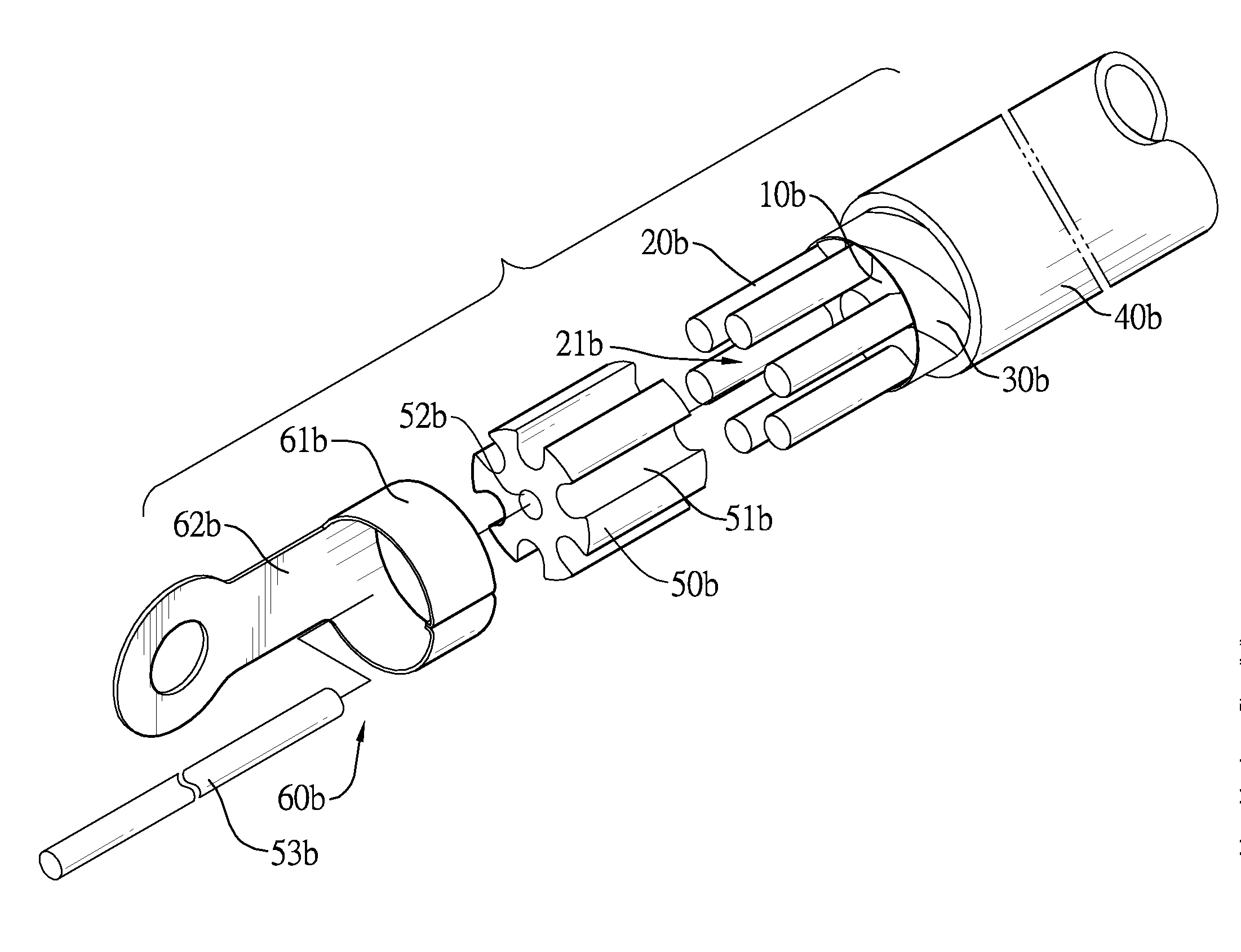
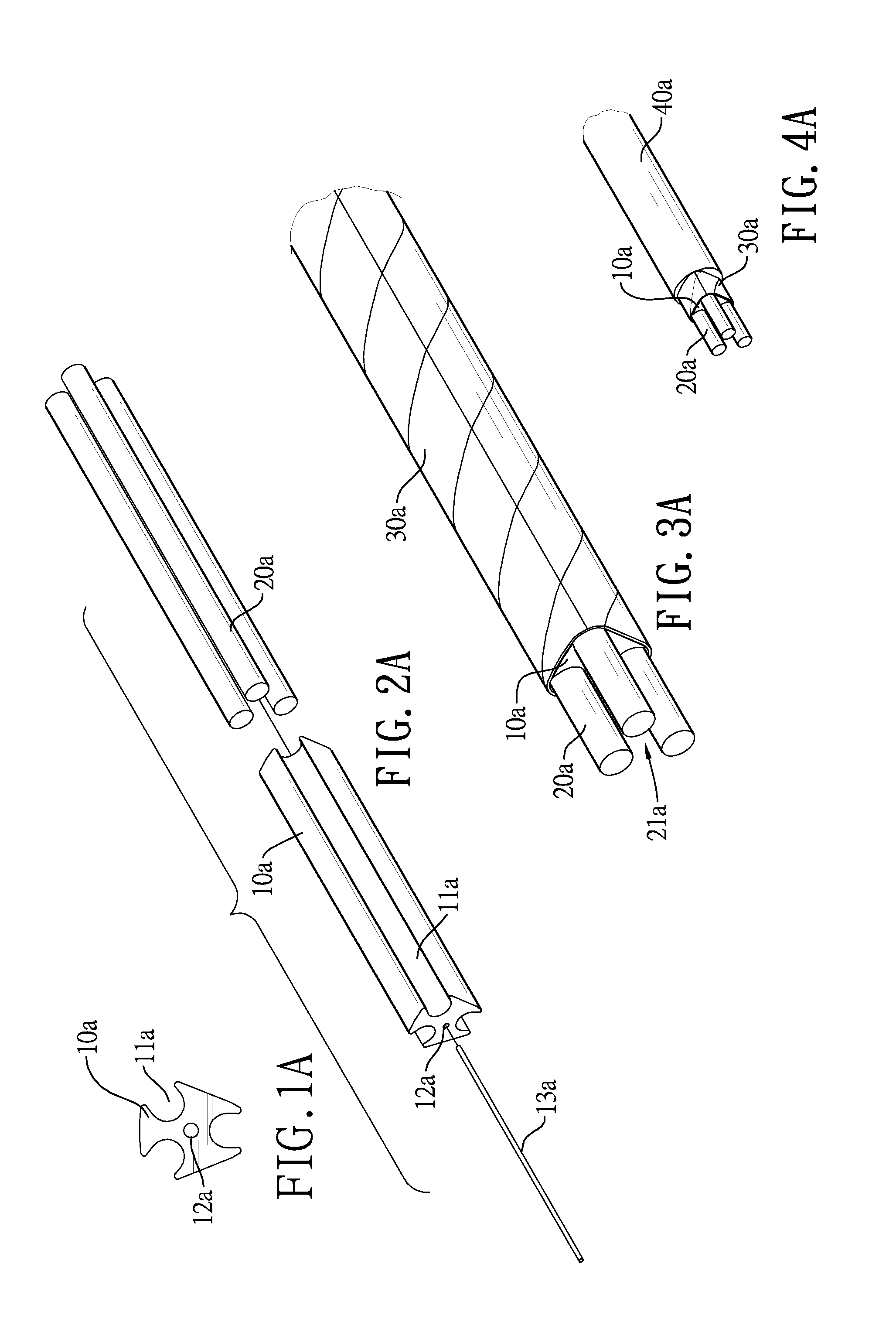
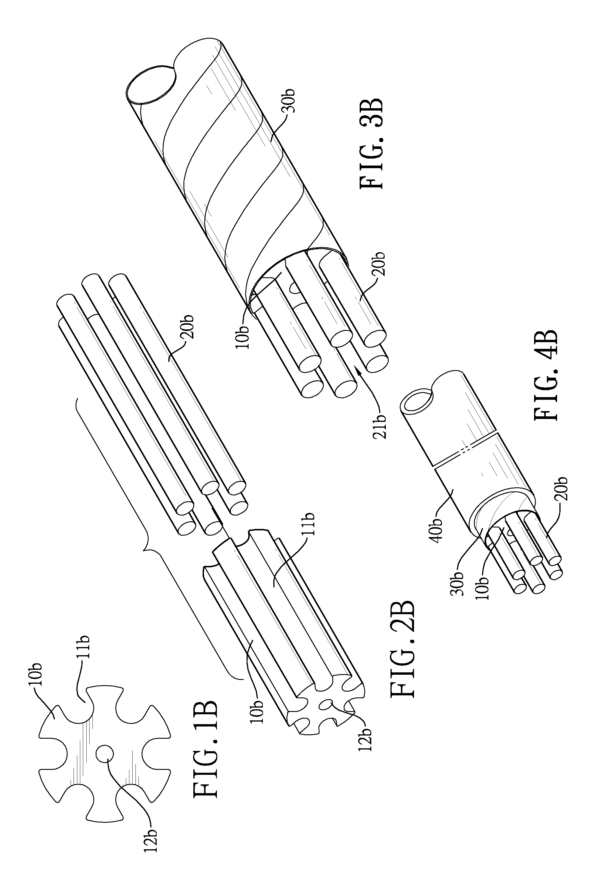
[0008]A cable in accordance with the present invention comprises a conductor keeper, multiple bare conductors, a dielectric tape, a plastic jacket and two copper cylinders. The conductor keeper has two end surfaces, an annular surface and multiple grooves. The grooves are formed longitudinally in the annular surface of the conductor keeper and are formed through two end surfaces of the conductor keeper. Each bare conductor is mounted in a corresponding groove of the conductor keeper and has a first end and a second end. The first end and second end of the bare conductor protrude out of the two end surfaces of the conductor keeper respectively so as to form two spaces. The dielectric tape is wrapped around the conductor keeper. The plastic jacket is coated around the dielectric tape. The copper cylinders are mounted in the spaces of the bare conductors respectively to make the bare conductors surround the copper cylinders and the bare conductors connect to each other in parallel. Therefore, the bare conductors can be fixed by the conductor keeper without being stranded by a stranding machine so production efficiency is improved while costs reduced. Furthermore, the bare conductors are connected in parallel via the copper cylinders so the skin effect can be minimized.

Problems solved by technology

However, the conductors 100 are stranded by a stranding machine and yet the stranding machine has disadvantages such as large working area and high equipment costs.

Method used


Image

  • Parallel structure high conductibility cable with conductor keeper
  • Parallel structure high conductibility cable with conductor keeper
  • Parallel structure high conductibility cable with conductor keeper

Examples


Embodiment Construction

[0029]With reference to FIGS. 1A to 4B, a cable in accordance with the present invention comprises a conductor keeper 10a,10b, multiple bare conductors 20a,20b, a dielectric tape 30a,30b and a plastic jacket 40a, 40b.

[0030]With reference to FIGS. 1A and 1B, the conductor keeper 10a,10b is a column, is made of plastic such as polyethylene (PE) or the like, is elongated and has two end surfaces, an annular surface, a central axis, multiple grooves 11a,11b and a through hole 12a,12b. The grooves 11a,11b are formed longitudinally in the annular surface of the conductor keeper 10a,10b and are formed through two end surfaces of the conductor keeper 10a,10b, and each groove 11a,11b has a concave bottom. The through hole 12a,12b is formed axially through the conductor keeper 10a,10b along the central axis. A poly wire 13a shown in FIG. 2A is mounted through the through hole 12a of the conductor keeper 10a to enhance the structural strength of the conductor keeper 10a. In preferred embodime...


PUM


Abstract

A cable has a conductor keeper, multiple bare conductors, a dielectric tape, a plastic jacket and two copper cylinders. The conductor keeper has multiple grooves. Each bare conductor is mounted in a corresponding groove of the conductor keeper and has a first end and a second end. The first end and second end of the bare conductor protrude out of the conductor keeper respectively so as to form two spaces. The dielectric tape is wrapped around the conductor keeper. The plastic jacket is coated around the dielectric tape. Two copper cylinders are mounted in the spaces of the bare conductors respectively to make the bare conductors surround the copper cylinders and the bare conductors connect to each other in parallel. Therefore, the skin effect is minimized and the bare conductors are efficient in that power consumption and emission of carbon dioxide during copper-smelting are significantly reduced.

Description

BACKGROUND OF THE INVENTION[0001]1. Field of the Invention[0002]The present invention relates to a cable, and more particularly to a high-conductibility and energy-saving cable.[0003]2. Description of the Prior Arts[0004]With reference to FIG. 13, a conventional cable is used to carry electric currents and comprises multiple conductors 100, a dielectric tape 200 and a plastic jacket 300. The conductors 100 are stranded and bonded together to form larger conductors that can be fixed to prevent disassembling. The dielectric tape 200 is wrapped around the conductors 100. The plastic jacket 300 is coated around the dielectric tape 200.[0005]However, the conductors 100 are stranded by a stranding machine and yet the stranding machine has disadvantages such as large working area and high equipment costs. Besides, electric currents tend to run along a surface of each conductor 100, known as the skin effect. The skin effect is a tendency of an alternating electric current (AC) to distribute...

Claims


Application Information

Patent Timeline
Patent Type & Authority Applications(United States)
IPC IPC(8): H01R4/00
CPCH02G3/0481
Inventor LIU, LI-WENLIU, WEI-JEN
Owner LIU LI WEN
Learn More