High-power light system

a high-power light and light system technology, applied in the direction of electrical appliances, etc., to achieve the effect of minimizing production, high manufacturing productivity, and maximizing actinide energy production

Active Publication Date: 2022-11-08
CARPE DIEM TECH
View PDF8 Cites 0 Cited by
  • Summary
  • Abstract
  • Description
  • Claims
  • Application Information

AI Technical Summary

Benefits of technology

[0013]It is yet another object of the present invention to provide a high-power light system of the type as described above which is designed to maximize the production of actinide energy, while minimizing the production of non-actinide energy, and in turn to treat any output heat generated therefrom.
[0014]It is still another object of the present invention to provide a high-power light system of the type as described above which allows for highly efficient manufacturing productivity and resultant product yield.
[0015]It is another object of the present invention to provide a high-power light system of the type as described above which has a limited number of parts, is inexpensive to manufacture and is easy to assemble.

Problems solved by technology

As a first shortcoming, the significant heat produced by high-power, LED-based lamps can transfer a considerable amount of infrared and non-reactive, or non-actinide, energy onto the substrate, which in turn can negatively affect its chemical and / or structural properties (e.g. resulting in thermal distortion due to locking in the shape at higher temperature or even actual burning or ignition of exposed surfaces).
Furthermore, excessive curing of the photoresist, which is affected by heat and dosage control, can cause the substrate to bond onto the master stamper of a nanoimprint lithography system, resulting in considerable complexity, or even damage, when separating the stamp from the substrate which is being imprinted.
As a second shortcoming, the significant thermal energy produced by high-power, LED-based lamps can render the banks of LEDs prone to overheating.
This generation of heat reduces the optical output of each LED due to its intrinsic operational properties (i.e. the power output of each LED decreases as temperature rises).
This additional current applied to each LED produces even more heat which further reduces output.
As can be appreciated, if improperly treated, extended overheating of the LEDs can result in permanent damage, thereby necessitating costly replacement.
As can be appreciated, restricting the power output of LED-based lamps, in turn, significantly limits overall manufacturing productivity and resultant product yield.

Method used


Image

  • High-power light system
  • High-power light system
  • High-power light system

Examples


Embodiment Construction

High-Power Light System 11

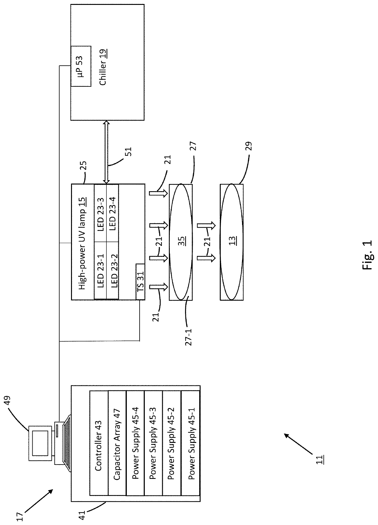
[0029]Referring now to FIG. 1, there is shown a simplified schematic representation of a high-power light system, the system being constructed according to the teachings of the present invention and identified generally by reference numeral 11. As will be explained in detail below, light system 11 is specifically designed to (i) emit high-power pulses of light of controlled energy dosage through a designated, user-modifiable, output cycle as well as (ii) monitor and treat any potentially-damaging temperature spikes resulting therefrom.

[0030]In the description that follows, system 11 is described in connection with the emission of ultraviolet (UV) light onto a semiconductor wafer-type substrate 13. In this capacity, light system 11 is particularly well-suited for use in curing photoresist applied onto substrate 13 (e.g. as part of the manufacture of miniature structures thereon). However, it should be noted light system 11 is not limited to curing applicatio...


PUM

PropertyMeasurementUnit
wavelengthsaaaaaaaaaa

Abstract

A high-power light system includes a lamp for producing light within a designated wavelength range, a chiller for maintaining the lamp below a defined temperature threshold, and a control module for regulating operation of both the lamp and the chiller. The lamp includes a plurality of light emitting diodes (LEDs) arranged into independently-operable modules. In use, the control module selectively overdrives the LEDs to yield high-power light within the designated wavelength range. To prevent overheating within the lamp, the control module restricts the lamp to a pulse-based operational cycle, whereby each period of LED activation is of limited duration and is immediately followed by a period of deactivation at least three times as long in duration as the period of activation. Additionally, one or more temperature sensors are disposed within the lamp and enable the control module to temporarily suspend LED activation when measured temperature levels exceed the defined threshold.

Description

CROSS-REFERENCE TO RELATED APPLICATIONS[0001]The present application claims the benefit under 35 U.S.C. 119(e) of U.S. Provisional Patent Application No. 62 / 799,931, which was filed on Feb. 1, 2019 in the names of John S. Berg et al., the disclosure of which is incorporated herein by reference.FIELD OF THE INVENTION[0002]The present invention relates generally to the fabrication of miniature structures and, more particularly, to high-power lamps used in the fabrication of miniature structures.BACKGROUND OF THE INVENTION[0003]High-power lamps are well-known in the art and are commonly used in connection with photolithography, nanoimprint lithography, and other similar processes related to the manufacture of miniature structures (e.g. semiconductors). For instance, one type of high-power lamp which is well known in the art is designed to produce light of a particular wavelength that, in turn, can be utilized to be selectively absorbed to cure photoresist which has been applied to a de...

Claims


Application Information

Patent Timeline
Patent Type & Authority Patents(United States)
IPC IPC(8): H05B45/18H05B47/14H05B47/17H05B47/28
CPCH05B45/18H05B47/14H05B47/17H05B47/28
Inventor BERG, JOHN S.BRANDSO, SONDRELEPINE, MATTHEW
Owner CARPE DIEM TECH
Why Eureka
Try Eureka