Vehicle braking system

Active Publication Date: 2011-08-11
ZF CV SYST EURO BV
View PDF9 Cites 12 Cited by
  • Summary
  • Abstract
  • Description
  • Claims
  • Application Information

AI Technical Summary

Benefits of technology

[0005]The present invention overcomes disadvantages associated with conventional braking systems and provides improved functionality and control response. Generally speaking, as described in greater detail hereinafter, the braking system according to embodiments of the present invention includes a pilot control valve with integral measuring capabilities (e.g., one or more pressure sensors) that quantitatively determines the brake pressure demanded by the vehicle driver. With the actual prevailing brake pressure being known, it can be controlled without, at the same time, having to discontinue the automatic braking function of the brake assist system. This results in improved control. Moreover, since the known brake pressure makes it possible to transmit an adequate brake pressure to the vehicle trailer system, the control accuracy of the trailer brake pressure is also enhanced. Additionally, a cost savings can be realized since air consumption can be reduced.

Problems solved by technology

A disadvantage of such known braking systems is that simultaneous feedback control by the brake assist system and active braking ordered by the driver is not possible.
Likewise, a quantitative determination of the brake pressure to be transmitted to the trailer is not possible in such known braking systems.

Method used


Image

  • Vehicle braking system
  • Vehicle braking system
  • Vehicle braking system

Examples


Embodiment Construction

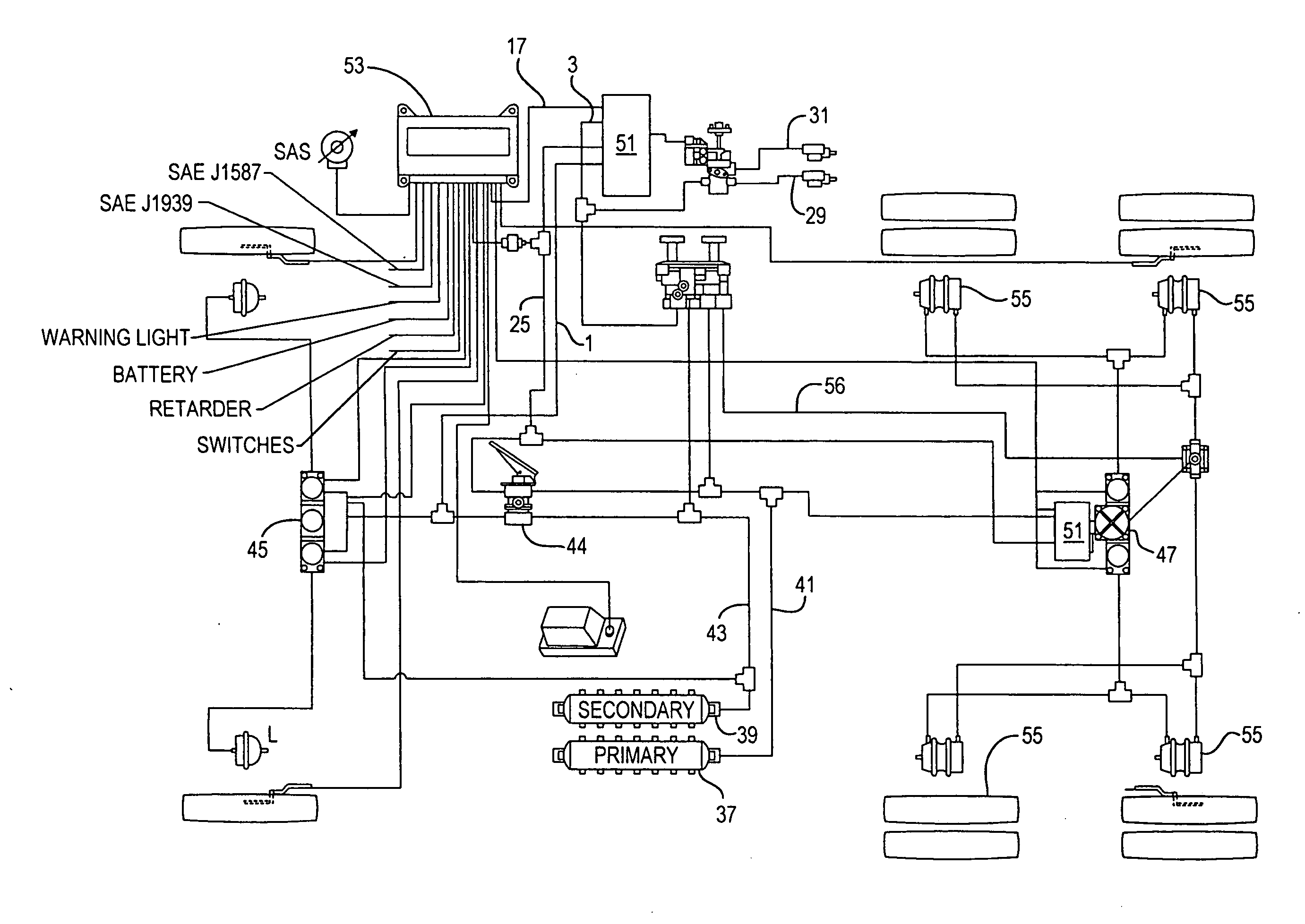
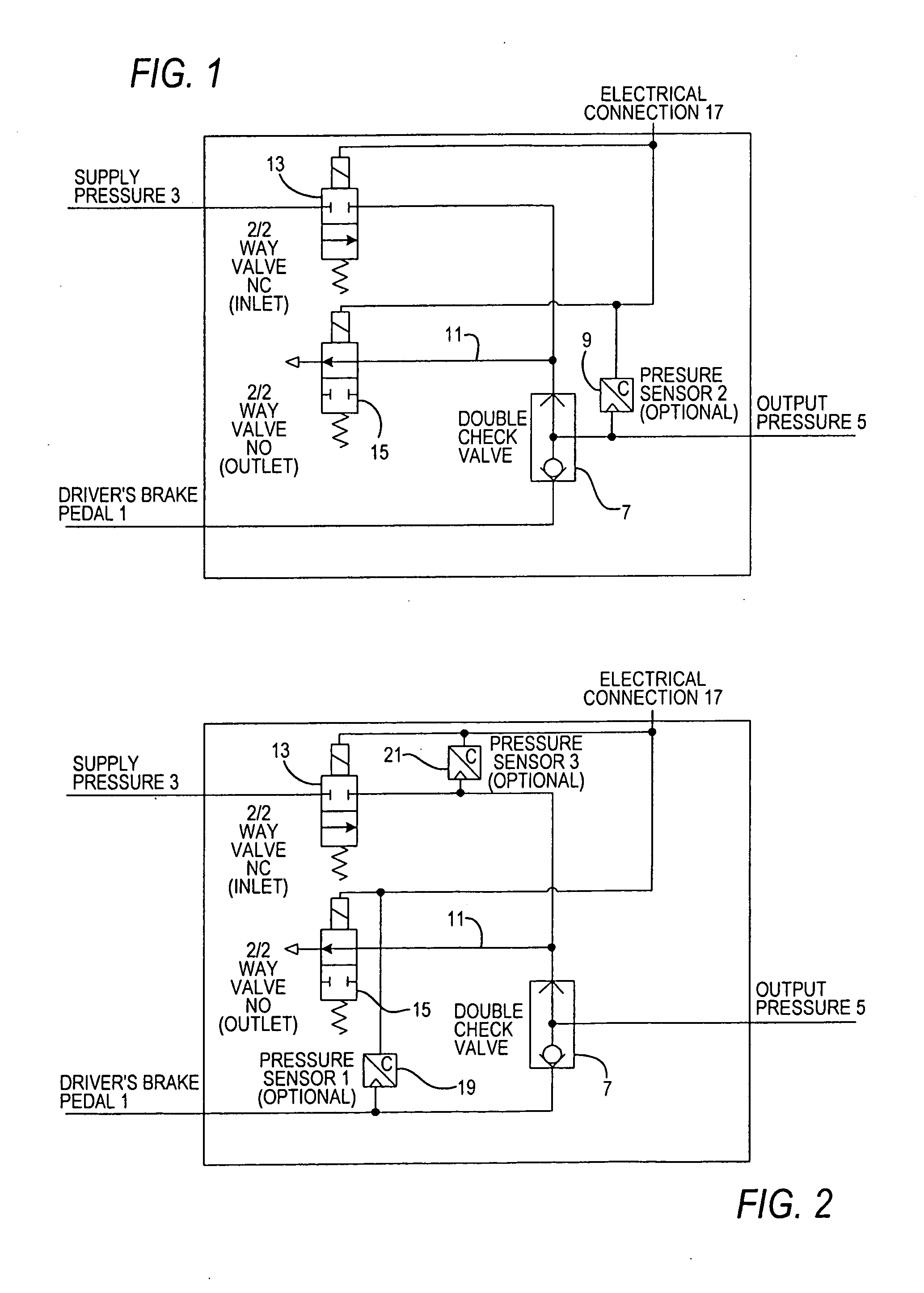
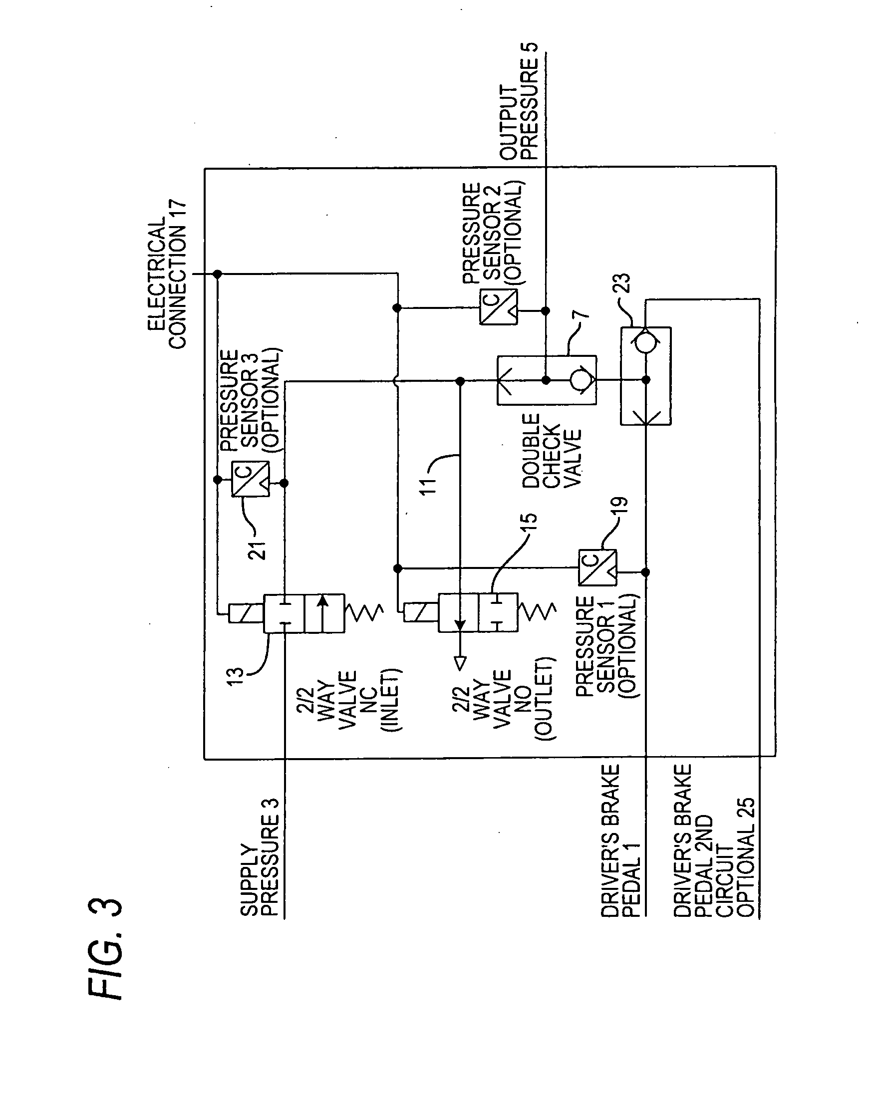
[0017]As stated above, the present invention provides an improved braking system including a pilot control valve with integral measuring capabilities that quantitatively determines the brake pressure demanded by the vehicle driver. The pilot control valve can be provided on a front axle brake circuit and / or a rear axle brake circuit of the vehicle tractor and on the brake circuit for a trailer. Integrating the measuring function into the pilot control valve makes the vehicle application easier and facilitates installation and servicing of the system.

[0018]Preferably, the measuring function outputs the brake pressure in the form of electrical signals. A plurality of known pressure sensors are suitably designed to measure a pressure and to convert this into a current or voltage signal. This signal can be polled by means of electrical lines from the sensors.

[0019]According to an embodiment of the present invention, a control unit receives and processes the signals corresponding to the ...


PUM


Abstract

An improved braking system and brake control method for a vehicle, in particular a truck, utilizes at least one pressure line for carrying a medium from at least one pressurized medium source to a brake device, and a brake pedal for receiving brake commands from a vehicle driver and for operating a brake line, which can be connected to the brake device. A pilot control valve with accompanying measuring capability quantitatively determines the brake pressure demanded by the vehicle driver.

Description

FIELD OF THE INVENTION[0001]The present invention generally relates to an improved braking system and method for a vehicle, in particular a truck, that quantitatively determine the brake pressure demanded by the vehicle driver.BACKGROUND OF THE INVENTION[0002]Known braking systems of the general type under consideration include at least one pressure line for carrying compressed air from at least one pressurized compressed air source to a brake device, and a brake pedal for receiving brake commands from a vehicle driver and for operating a brake line, which can be connected to the brake device. Such systems are used in trucks as well as in other vehicle types.[0003]Trucks are often equipped with driving assistance systems that also include systems that actively control braking performance. With the aid of various sensors, such brake assist systems register the driving situation at any given time and, in specific situations, undertake braking operations according to the evaluation of ...

Claims


Application Information

Patent Timeline
IPC IPC(8): B60T8/176B60T11/10B60T11/12B60T11/28B60T8/1755B60T8/32
CPCB60T8/327B60T15/181B60T8/4818
Inventor WOHLTMANN, DIRKWOLF, THOMASLENZ, THOMAS
Owner ZF CV SYST EURO BV
Why Eureka
Try Eureka