
Recordable optical disk, recording device, recording method, and reproduction device

a recording optical disk and recording method technology, applied in the direction of digital signal error detection/correction, recording signal processing, instruments, etc., can solve the problems of indefinite degree of influence on the other layers, inability to predict the effect of transmittance change, and difficulty in designing the opc area in the respective recording layer and designing the area where various kinds of management, etc., to achieve the effect of reducing the influence of transmittance chang

Active Publication Date: 2011-08-11
SONY CORP +4
View PDF10 Cites 9 Cited by
  • Summary
  • Abstract
  • Description
  • Claims
  • Application Information

AI Technical Summary

Benefits of technology

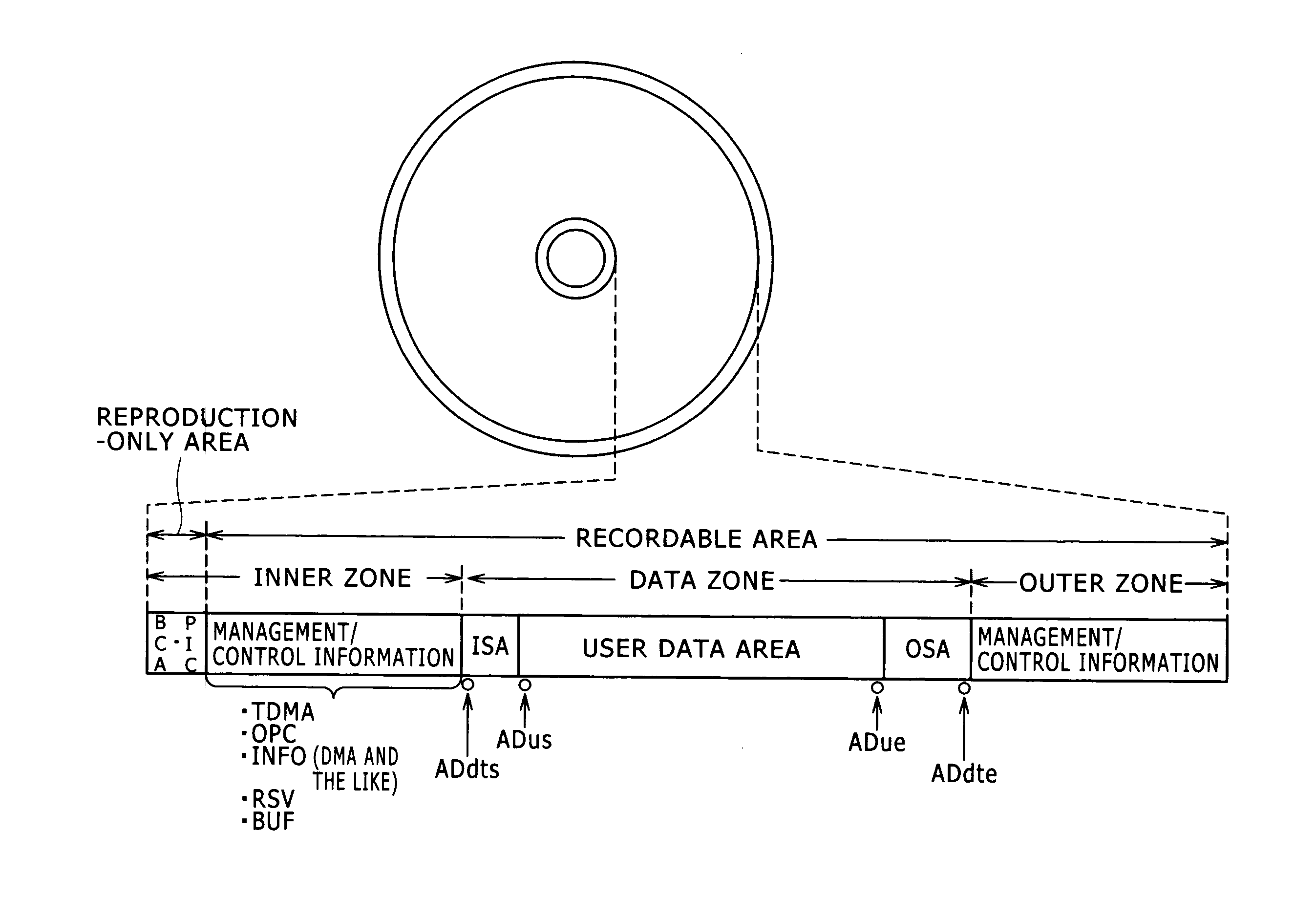
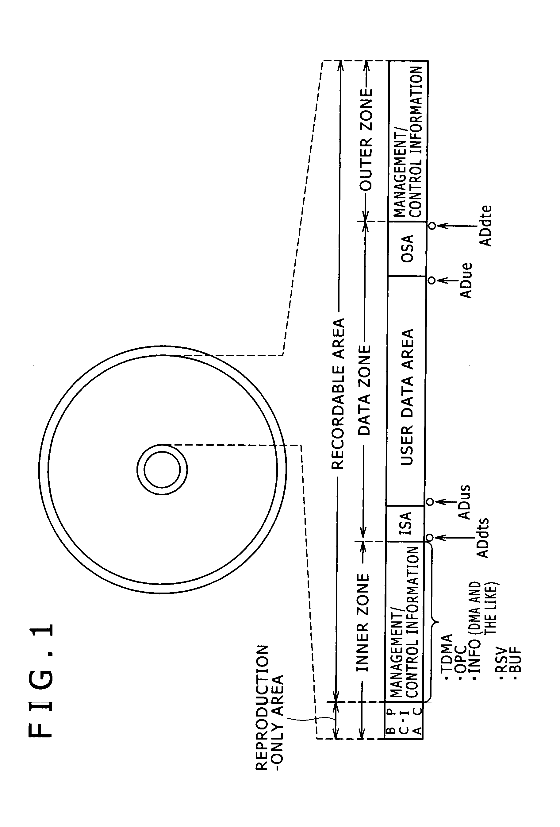
[0025]According to another embodiment of the present invention, there is provided a recording device for a recordable optical disk as a plural-layer disk that includes at least three recording layers provided over a disk substrate and an optically-transparent layer formed on a laser-incident surface side. The recording device includes a controller configured to dispose a test area for laser power control about a respective one of the recording layers in an inner circumference side area closer to an inner circumference than a data zone in which user data is recorded in the respective one of the recording layers of the recordable optical disk in such a way that the test areas are prevented from overlapping with each other in a layer direction, the controller carrying out control to perform information recording after laser power adjustment by use of the disposed test area.
[0031]The embodiments of the present invention offer an advantage that, in a recordable multi-layer optical disk such as a triple-layer disk and a quadruple-layer disk, proper arrangement in the inner circumference side area can be realized and proper OPC operation and recording / reproduction of management information are allowed.

Problems solved by technology

In the development of an optical disk including at least three layers, it is difficult to design the OPC areas in the respective recording layers and design the areas where various kinds of management information are recorded and reproduced.
Moreover, due to the dependency of the transmittance change on the recording power, the degree of the influence on the other layers is indefinite and the transmittance change cannot be predicted.

Method used


Image

  • Recordable optical disk, recording device, recording method, and reproduction device
  • Recordable optical disk, recording device, recording method, and reproduction device
  • Recordable optical disk, recording device, recording method, and reproduction device

Examples


Embodiment Construction

[0058]An embodiment of the present invention will be described below in the following order.

[1. Disk Structure]

[2. DMA]

[3. TDMA]

[4. Plural-layer Disk / Inner Zone of Existing Double-layer Disk]

[5. Inner Zone of Triple-layer Disk of Embodiment]

[6. Inner Zone of Quadruple-layer Disk of Embodiment]

[7. Disk Drive Device]

[1. Disk Structure]

[0059]First, the outline of an optical disk of the embodiment will be described. This optical disk can be implemented as a write-once disk (BD-R) or a rewritable disk (BD-RE) in the category of a high-density optical disk system referred to as the so-called Blu-ray Disc.

[0060]One example of the physical parameters of the high-density optical disk of the present embodiment will be described.

[0061]As the disk size of the optical disk of the present example, the diameter is 120 mm and the disk thickness is 1.2 mm. That is, from these points, this optical disk is the same as a disk of the CD (Compact Disc) system and a disk of the DVD (Digital Versatile Disc...


PUM


Abstract

The present invention is to realize a proper inner zone layout in an optical disk having at least three layers. A test area is provided in the inner zone (inner circumference side area) in each of recording layers. The test areas of each layer are so disposed as to be prevented from overlapping with each other in the layer direction. Furthermore, the number of management information recording / reproduction areas overlapping with the test area in the layer direction at a position closer to the laser-incident surface than this test area is set equal to or smaller than one in each test area of each recording layer. The management information recording / reproduction areas are each so disposed as to be prevented from overlapping with the test areas in the respective recording layers in the layer direction on the disk substrate side of the test areas.

Description

TECHNICAL FIELD[0001]The present invention relates to a recordable optical disk such as a write-once disk and a rewritable disk, a recording device capable of dealing with a recordable optical disk, a recording method, and a reproduction device.BACKGROUND ART[0002]Optical recording media such as the Blu-ray Disc (registered trademark) are known. In the optical recording media, recording and reproduction of information by use of a semiconductor laser are performed.[0003]The recording to an optical disk by use of a semiconductor laser is greatly affected by variation in the laser power attributed to the temperature and change over time, various kinds of skews and offsets attributed to an adjustment error at the time of the manufacturing, and a recording condition gap in the drive control. Therefore, particularly for recordable optical disks such as a write-once disk and a rewritable disk, variation in the laser drive circuit and the optical element is suppressed and precise light-emis...

Claims


Application Information

Patent Timeline
IPC IPC(8): G11B20/10G11B7/24G11B19/00
CPCG11B2020/1275G11B7/24038G11B7/1267G11B2220/2541G11B2220/235G11B20/1217G11B2007/0013G11B7/00736G11B7/007G11B7/125G11B7/0045G11B20/10
Inventor AKIMOTO, YOSHIHIROKOBAYASHI, SHOEIITO, MOTOSHIHINO, YASUMORIINOUE, HIROYASUMIYAMOTO, HARUKAZUNISHIMURA, KOICHIROHWANG, SUNG-HEEHWANG, IN-OH
Owner SONY CORP
Learn More