Shaft furnace and method for heat-treating moulded bodies containing carbon

a shaft furnace and heat-treatment moulding technology, which is applied in vertical furnaces, furnaces, lighting and heating apparatuses, etc., can solve the problems of limited production capacity to the height of the moulded body column, uneven electrode consumption, and limited production capacity, so as to reduce volumetric flow and prevent the formation of a temperature gradient

Active Publication Date: 2011-08-11
LEISENBERG WOLFGANG
View PDF5 Cites 2 Cited by
  • Summary
  • Abstract
  • Description
  • Claims
  • Application Information

AI Technical Summary

Benefits of technology

[0007]The present invention is based on the objective of proposing a shaft furnace and a method for heat-treating moulded bodies containing carbon in a shaft furnace which respectively make it possible to thermally act upon the moulded bodies in a largely uniform fashion such that the formation of a temperature gradient is prevented.
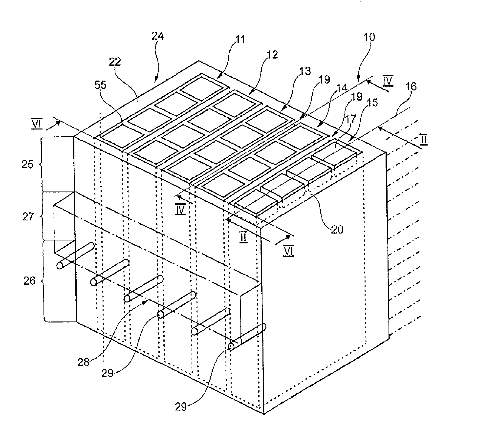
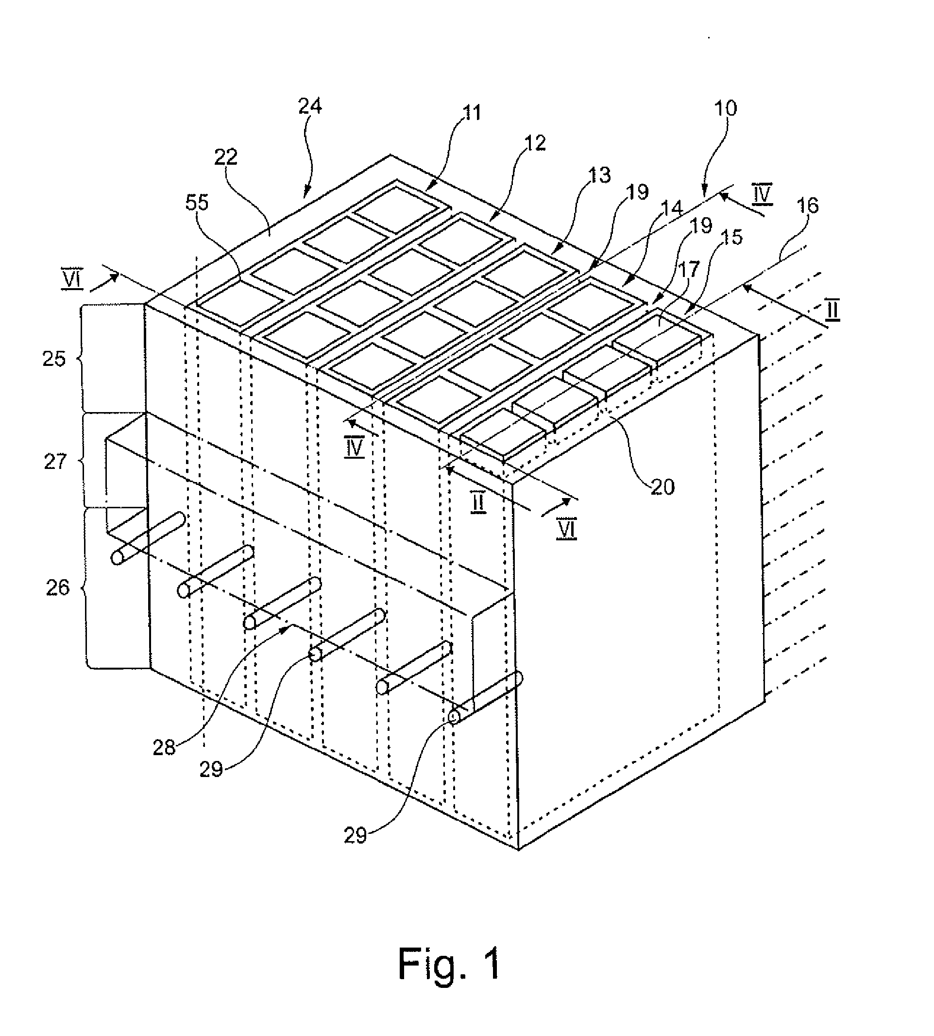
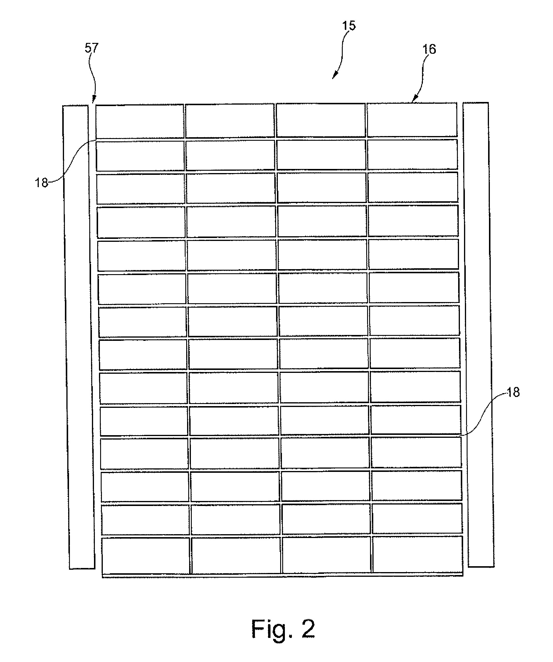
[0008]This objective is attained according to the invention with the characteristics of a shaft furnace in that the shaft furnace (10) for heat-treating moulded bodies containing carbon, particularly anodes (17), with an arrangement of the moulded bodies in at least one moulded body column (11 to 15) that is arranged between tempering shafts (19, 20, 21) and features in a conveyor shaft (57) a plurality of moulded body rows (16) that are arranged on top of one another, wherein these moulded body rows are moved past a plurality of temperature zones (60 to 73) of the tempering shafts (19, 20, 22) on their path from an inlet temperature zone (60) to an outlet temperature zone (73) and pass through a heating zone (25), a firing zone (27) that is provided with a burner device (28) and a cooling zone (26), is characterized in that thermally insulating intermediate layers (32, 18) are arranged between the temperature zones (60 to 73) of the tempering shaft (19, 20, 22), as well as between the moulded body rows of the moulded body column. Additional, particularly beneficial, embodiments of the invention are provided in accordance with the following subsidiary shaft furnace devices.
[0009]In accordance with a second shaft furnace embodiment of the invention, the first embodiment is modified so that the temperature zones (60 to 73) of the tempering shafts (19, 20, 22) feature channels (42) that extend in the longitudinal direction of the moulded body rows (16) and are connected to one another on their ends by means of deflection devices (43) in order to form a channel arrangement (41) that ascends in a serpentine-like fashion. In accordance with a third shaft furnace embodiment of the invention, the second embodiment is modified so that at least one throttle device for reducing the volumetric flow in an upstream temperature zone area (51) is provided in the channel arrangement (41) of a temperature zone (60 to 73). In accordance with a fourth shaft furnace embodiment of the invention, the second embodiment and the third embodiments are modified so that the channels (42) are three-dimensionally angled such that the channels from an upstream temperature zone area (51) proportionally extend in a downstream temperature zone area (52) and vice versa. In accordance with a fifth shaft furnace embodiment of the invention, the first embodiment, the second embodiment, the third embodiment, and the fourth embodiment are modified so that a bypass (47) for directly connecting two adjacent channels (42) to one another is provided in the flow inlet area (46) of a temperature zone (60 to 73).
[0010]This objective is also attained according to the invention with the characteristics of a shaft furnace according to a sixth embodiment of the invention in that the shaft furnace (10) for heat-treating moulded bodies containing carbon, particularly anodes (17), with an arrangement of the moulded bodies in at least one moulded body column (11 to 15) that is arranged between tempering shafts (19, 20, 21) and features in a conveyor shaft (57) a plurality of moulded body rows (16) that are arranged on top of one another, wherein these moulded body rows are moved past a plurality of temperature zones (60 to 73) of the tempering shafts (19, 20, 22) on their path from an inlet temperature zone (60) to an outlet temperature zone (73) and pass through a heating zone (25), a firing zone (27) that is provided with a burner device (28) and a cooling zone (26), is characterized in that the shaft furnace features at least two conveyor shafts (57) for the simultaneous heat treatment of a plurality of moulded body columns, wherein a heating shaft (19, 20, 22) for the simultaneous heat treatment of both moulded body columns being conveyed in the conveyor shafts is arranged between the conveyor shafts, and wherein temperature zones (66, 67, 68) of the tempering shafts situated in the firing zone are provided with burners (29) of the burner device (28) that are arranged in such a way that the temperature zones are thermally acted upon tangentially to the moulded body rows. Additional, particularly beneficial, embodiments of the invention are provided in accordance with the following subsidiary shaft furnace devices.
[0011]In accordance with a seventh shaft furnace embodiment of the invention, the sixth embodiment is modified so that the burners (29) are arranged in such a way that the temperature zones (66, 68, 69) are thermally acted upon in the longitudinal direction of the temperature zones.
[0012]In another embodiment of the invention, a shaft furnace, for heat-treating molded bodies containing carbon, for example, anodes, is characterized in that the shaft furnace comprises a heating zone; a firing zone provided with a burner device; a cooling zone; a plurality of tempering shafts, passing through the heating zone, firing zone and cooling zone, and defining a molded body column space arranged to contain at least one molded body column, wherein the molded body column space is divided into a plurality of temperature zones; a plurality of thermal insulating layers separating each temperature zone of the molded body column space and thereby defining a stack of molded body row spaces; and a conveyor shaft disposed to convey the stack of molded body row spaces through the shaft furnace.

Problems solved by technology

The realization in the form of only one moulded body column also limits the production capacity to the height of the moulded body column.
Based on the known method and the known device used for carrying out this method, the production capacity therefore can only be increased by correspondingly multiplying the entire furnace such that the installation of a complete system with increased production capacity also has a corresponding space requirement.
Analogous to the continuous transport of the moulded body rows between the tempering shafts, the lateral arrangement of the burner devices promotes a non-uniform temperature distribution in the moulded bodies due to the formation of so-called “hot spots” such that moulded bodies with an irregular structure are produced and one has to accept the corresponding disadvantageous effects that, if the moulded bodies are realized in the form of anodes, manifest themselves in the form of an uneven electrode consumption.

Method used


Image

  • Shaft furnace and method for heat-treating moulded bodies containing carbon
  • Shaft furnace and method for heat-treating moulded bodies containing carbon
  • Shaft furnace and method for heat-treating moulded bodies containing carbon

Examples


Embodiment Construction

[0047]FIG. 1 shows a shaft furnace 10 with a plurality of moulded body columns in the form of anode columns 11, 12, 13, 14, 15 that respectively feature moulded body rows in the form of anode rows 16 that are arranged on top of one another and respectively comprise four moulded bodies in the form of anodes 17 that are arranged in a row.

[0048]In the embodiment illustrated in FIG. 1, 14 anode rows in all are arranged such that they lie on top of one another, wherein only the top anode rows 16 is respectively illustrated in order to provide a better overview. FIG. 2 shows the anode column 15 in the form of a sectional representation through the fourteen anode rows 16 that are arranged on top of one another and respectively separated from one another in the vertical direction by a thermally insulating intermediate layer 18. The intermediate layer 18 is preferably realized in the form of a fire-resistant insulating layer of lightweight dead clay. The intermediate layer may be realized in...


PUM

PropertyMeasurementUnit
temperatureaaaaaaaaaa

Abstract

The invention relates to a shaft furnace (10) and a method for heat treating carbonaceous molded parts, particularly anodes (17), having an arrangement of the molded parts in at least one molded part column (11 to 15) disposed between tempering shaft devices (19, 20, 21) comprising a plurality of molded part rows (16) disposed above each other in a conveyor shaft, the rows being moved past temperature fields of the tempering shaft devices (19, 20, 22) and passing through a heating zone (25), a firing zone (27) having a burner device (28), and a cooling zone (26), wherein thermally insulating intermediate layers are disposed both between the temperature fields of the tempering shaft devices (19, 20, 22) and between the molded part rows of the molded part columns.

Description

[0001]This is a National Phase Application in the United States of International Patent Application No. PCT / EP2008 / 060064, filed Jul. 31, 2008, the entire disclosure of which is incorporated herein by reference.FIELD OF THE INVENTION[0002]The present invention pertains to a shaft furnace for heat-treating moulded bodies containing carbon, particularly anodes, with an arrangement of the moulded bodies in at least one moulded body column that is arranged between tempering shafts and features in a conveyor shaft a plurality of moulded body rows that are arranged on top of one another, wherein these moulded body rows are moved past a plurality of temperature zones on their path from an inlet temperature zone to an outlet temperature zone and pass through a heating zone, a firing zone that is provided with a burner device and a cooling zone. The invention furthermore pertains to a method for heat-treating moulded bodies containing carbon, particularly anodes.BACKGROUND OF THE INVENTION[0...

Claims


Application Information

Patent Timeline
Patent Type & Authority Applications(United States)
IPC IPC(8): F27D9/00
CPCF27B9/142F27B1/005Y02P40/60
Inventor LEISENBERG, WOLFGANG
Owner LEISENBERG WOLFGANG
Why Eureka
Try Eureka