Trimmable pod drive

a technology of a pod drive and a trough, which is applied in the direction of marine propulsion, vessel parts, vessel construction, etc., can solve the problems of reducing thrust efficiency and vessel speed, increasing drag, and reducing forward thrust, so as to improve trimming performance

Active Publication Date: 2011-08-11
AXIAL DRIVE SYST LLC
View PDF12 Cites 14 Cited by
  • Summary
  • Abstract
  • Description
  • Claims
  • Application Information

AI Technical Summary

Benefits of technology

[0011]The present inventors have recognized the aforementioned difficulties and the need for improved trimming performance and have recognized that it would be possible to move a pod drive in a trimming manner. Further, the present inventors have recognized that it would be desirable to provide a mechanism to allow controlled trim to occur during the operation of a marine vessel in negative and positive trim angles with a pod drive that protrudes through the bottom of a vessel.

Problems solved by technology

Although the drive may be allowed to steer through 360 degrees along its steering axis, the steering axis is fixed to the hull and cannot be altered.
Exerting the device against the surface of the water creates a parasitic drag force that reduces thrust efficiency and vessel speed.
As with the trim tab, the use of two pod drives can provide another method of pitch control, although it is also problematic.
Although pitch control can be obtained in this manner, a practical problem with this method of trim is that in order to trim the vessel, forward thrust must be attenuated.
Additionally, toeing the gear cases causes increased drag.
Therefore, this method may be just as inefficient or possibly even worse than using trim tab or interceptor methodology.

Method used


Image

  • Trimmable pod drive
  • Trimmable pod drive
  • Trimmable pod drive

Examples


first embodiment

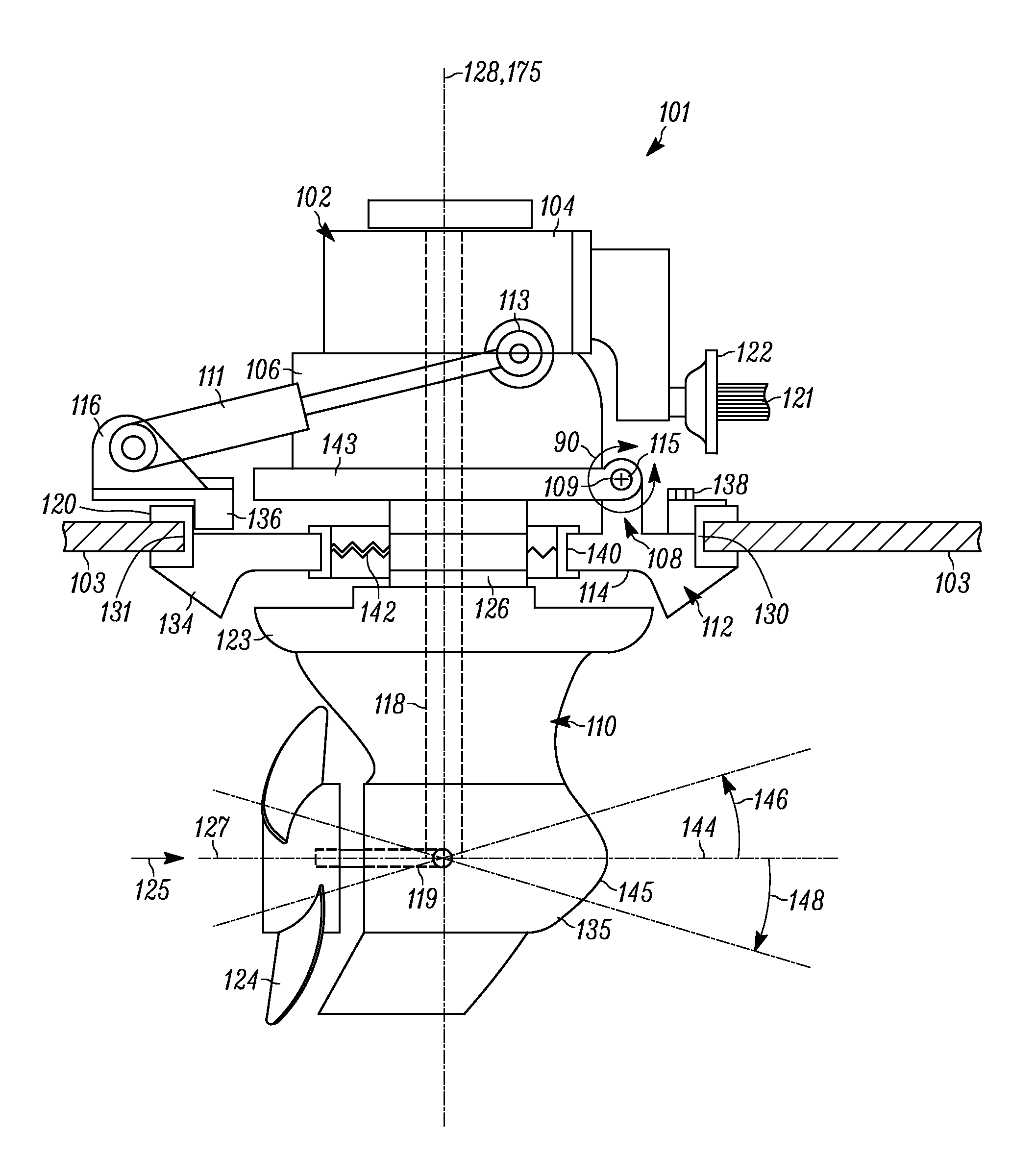
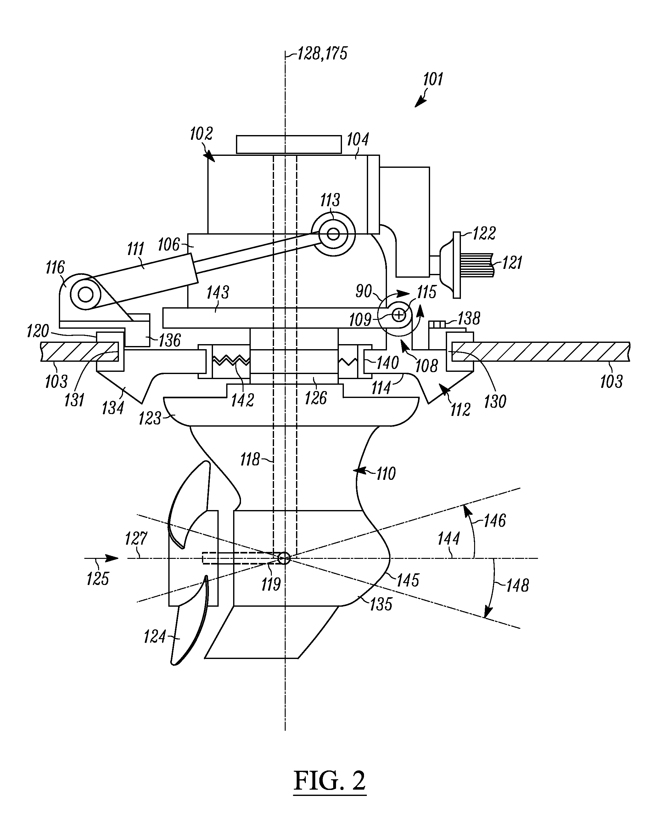
[0041]Referring to FIG. 2, the exemplary trimmable pod drive assembly 101 is illustrated. The trimmable pod drive assembly 101 includes a pod drive unit 102 and a trim assembly 108. The pod drive unit 102 includes a transmission assembly 104, a steering unit 106, and a gear case assembly 110. The trim assembly 108 can be used to rotate the pod drive unit 102 about a trim axis 109 (point of rotation) using one of a plurality of configurations, to provide a trim or tilt adjustment. Although a further reference to “tilt” is not included, it should be understood that the use of the term “trim” in various forms can include “tilt” (e.g. trim / tilt axis, trim / tilt adjustment, etc.). In general, in at least some embodiments, the trim assembly can merely include components that are at least in part or are in whole, integrally formed with various features of the vessel and / or pod drive unit. Similarly, various specific components described below as included in the various embodiments of the tr...

third embodiment

[0049]Referring to FIG. 4, an exemplary trimmable pod drive assembly 101b is illustrated. In this configuration, a trim assembly 108b includes a mounting plate 112b includes a pair of arc-shaped supports 137b that extend upwards away from a vessel bottom portion 103b and inwards toward a steering unit 106b. The supports 137b are fastened to the vessel bottom portion 103b by a plurality of fixed mounts 141b. One or more trim cylinder(s) 111b is attached at one end to a rear pivot mount 116b and at the other end to a pivoting mount 113b at the steering unit 106b. The steering unit 106b can be secured to a pivot plate 143b, which is secured to pivot mounts 114b on the arc-shaped supports 137b by a pivot pin 115b. Rotation of a pod drive unit 102b is fixed at a trim axis 109b, which is centered about the pivot pin 115b. The mounting plate 112b of this configuration allows for the trim axis 109b to be raised a desired distance above the vessel bottom portion 103b to accommodate various d...

fourth embodiment

[0050]Referring to FIG. 5, an exemplary trimmable pod drive assembly 101c is illustrated. As seen in FIG. 5, in at least some embodiments, the trimmable pod drive assembly 101c can be secured to a stringer system 117c, rather than directly to the vessel bottom portion 103c. A stringer system for a marine vessel is well known in the art and includes a series of generally parallel longitudinally disposed stringers positioned in the hull of a vessel along the vessel bottom for strengthening the vessel bottom and for providing a mounting point for power train devices to be fastened to the hull of the vessel without the need to penetrate the vessel bottom.

[0051]To secure the trimmable pod drive assembly 101c to the stringer system 117c, a trim assembly 108d includes a mounting plate 112c secured to a plurality of mounting blocks, which are secured to the stringers 151c. In at least some embodiments, a pair of stringers 151c will each have front and rear mounting blocks 152c, 154c that se...


PUM


Abstract

Disclosed herein is a trimmable pod drive assembly that includes a pod drive unit having a transmission assembly secured to a steering unit, a gear case assembly coupled to and rotatable by the steering unit about a steering axis, and a propeller rotatable about a propeller driveshaft axis extending through the gear case assembly so as to generate thrust along a thrust vector. The trimmable pod drive assembly further includes a trim assembly secured to the pod drive unit in a manner allowing for rotation of the pod drive unit about a trim axis that is substantially perpendicular to the steering axis, wherein actuation of at least one component of the trim assembly causes movement of the pod drive unit and the thrust vector about the trim axis.

Description

CROSS-REFERENCE TO RELATED APPLICATIONS[0001]The present application claims the benefit of U.S. provisional patent application No. 61 / 303,513 filed on Feb. 11, 2010 and entitled “Trimable Pod Drive”, and U.S. provisional patent application No. 61 / 337,631 filed on Feb. 11, 2010 and entitled “Trimable Pod Drive”, which are hereby incorporated by reference herein.FIELD OF THE INVENTION[0002]The trimmable pod drive relates to marine vessel pod drive units.BACKGROUND OF THE INVENTION[0003]Modern inboard boat technology includes several types of drive units that are suitable for providing propulsion to large marine vessels, namely, inboard-fixed strut drive and pod drive. Both drive units are similar in that an engine is rigidly mounted inside the vessel to a hull structure (a.k.a. stringer system) along the hull, and a drive or shaft system is also rigidly mounted separately to the hull so that power can be applied through the shaft system and the resulting propulsive forces can be chann...

Claims


Application Information

Patent Timeline
Patent Type & Authority Applications(United States)
IPC IPC(8): B63H23/00
CPCB63H23/02B63H5/125B63H25/42B63H2005/1256
Inventor DAVIS, ERIC A.DAVIS, RICHARD A.
Owner AXIAL DRIVE SYST LLC
Why Eureka
Try Eureka