
Apparatus and method for inspection of underground pipes

a technology for underground pipes and apparatuses, applied in the direction of pipes, gas/liquid distribution and storage, reradiation, etc., to achieve the effect of facilitating data transmission

Active Publication Date: 2011-08-11
SEWERVUE TECH CORP
View PDF13 Cites 42 Cited by
  • Summary
  • Abstract
  • Description
  • Claims
  • Application Information

AI Technical Summary

Benefits of technology

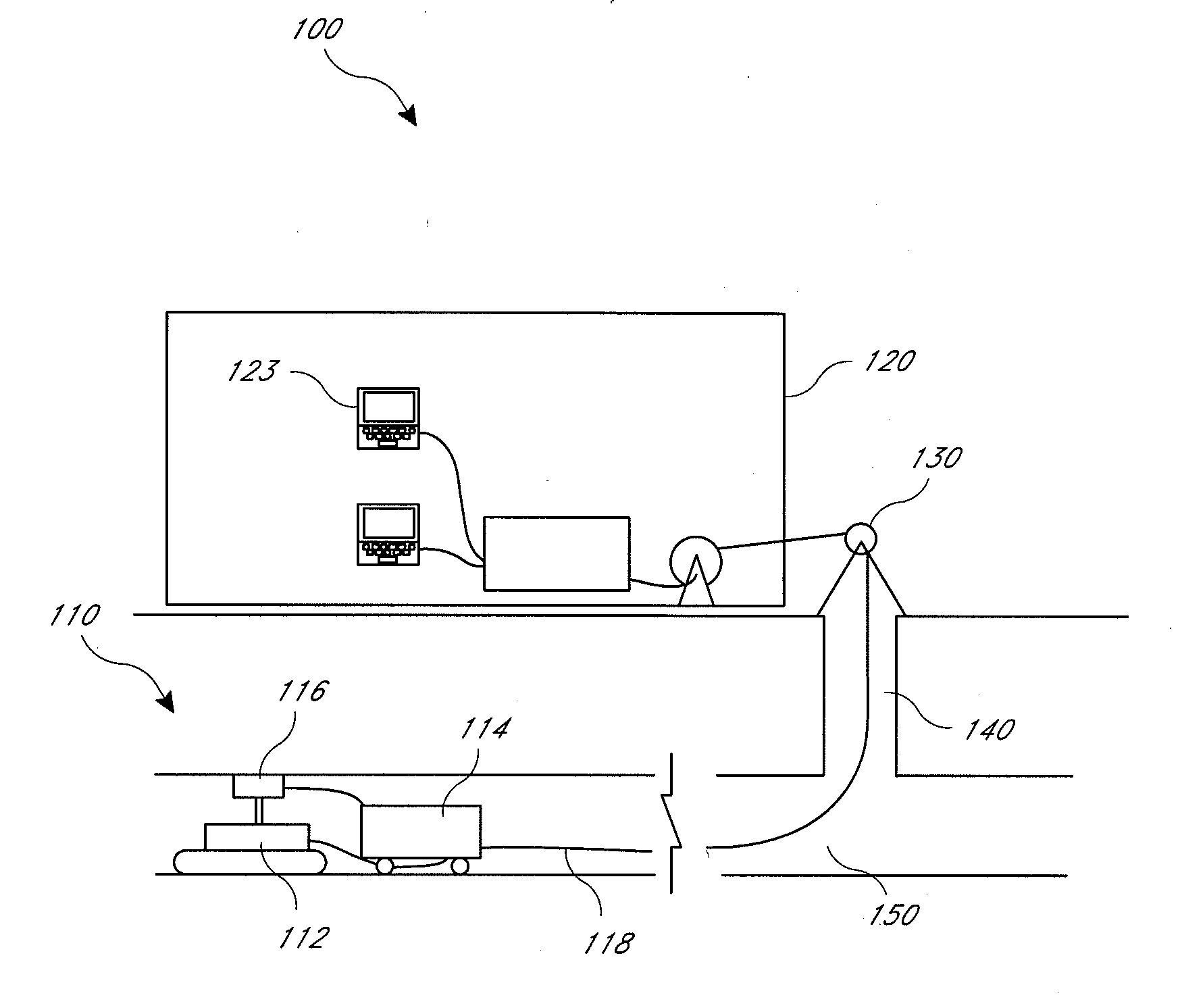
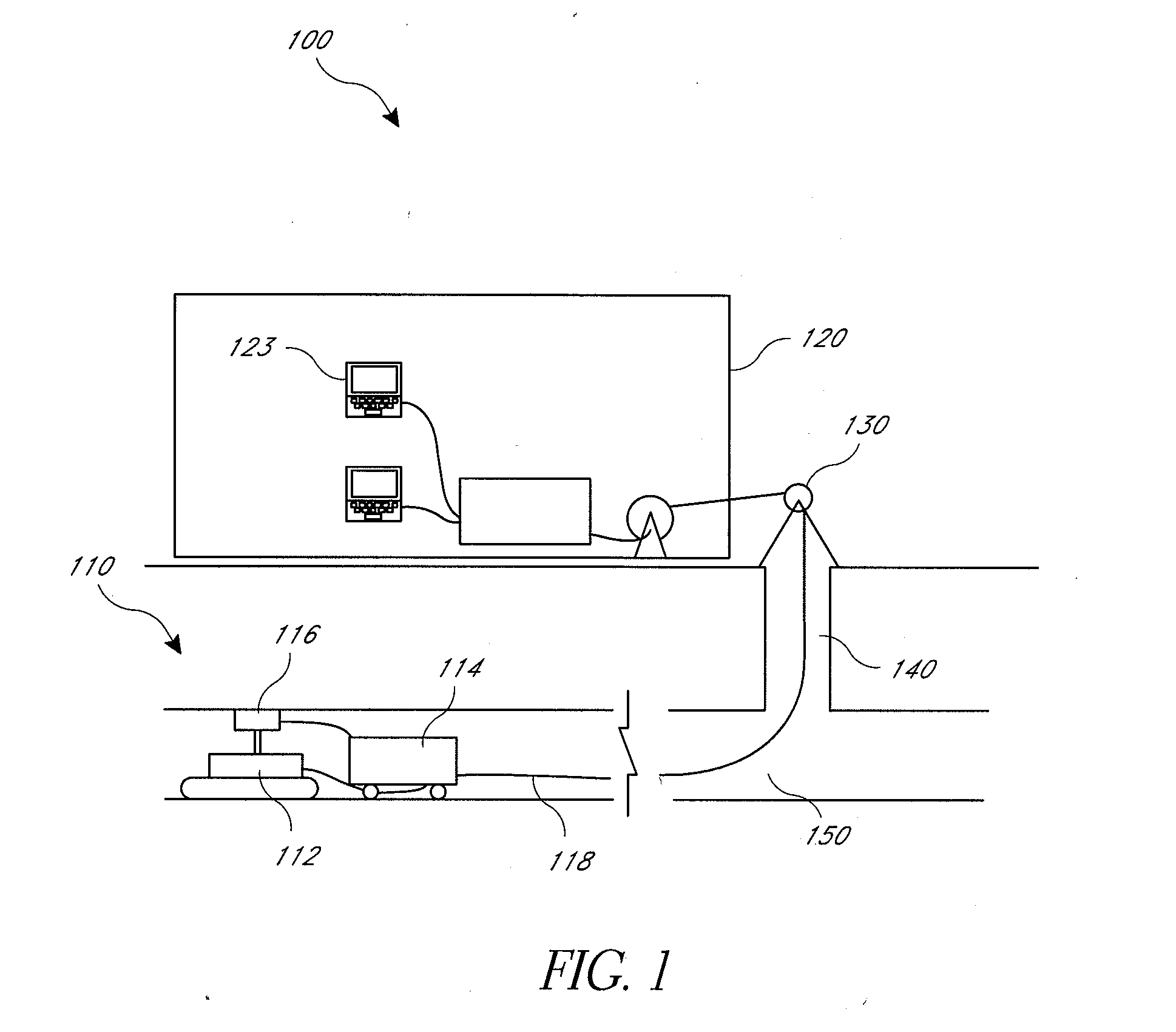
[0013]In certain embodiments, the system includes an above-ground control subsystem that provides at least one control signal to the data acquisition subsystem, wherein the data acquisition subsystem is responsive to the at least one control signal to control one or more aspects of the data acquisition subsystem. The data acquisition subsystem and / or the data storage subsystem may be tethered to the above-ground control system by a data conduit having a cross-sectional area of less than 0.2 square inches, and / or having a length of greater than 100 meters.
[0014]The data acquisition subsystem may include one or more cameras. The one or more cameras may include one or more wide-spectrum cameras. For example, the data acquisition subsystem may include at least one camera facing in a forward direction with respect to a direction of travel of the data acquisition device within the conduit, at least one camera facing in a direction substantially opposite to the forward direction
[0015]Certain embodiments provide an apparatus for inspecting an underground conduit from within. The apparatus may include a data acquisition device configured to be placed within the conduit and to move along a first portion of the conduit to obtain data regarding the first portion of the conduit and a memory device configured to be positioned within the conduit and operationally coupled to the data acquisition device while positioned within the conduit, travel along a second portion of the conduit, and store at least a portion of the data from the data acquisition device for retrieval after the data acquisition device has moved along the first portion of the conduit. The memory device may be contained within a container that is liquid-tight. The memory device may be configured to provide wireless accessibility to data stored by the memory device. The container may comprise a lid configured to be manually removable to facilitate data transmission by providing physical access to the memory device. The second portion of the conduit may be coextensive with at least some of the first portion of the conduit.
[0016]Certain embodiments provide a method for inspecting an underground conduit from within. The method may include introducing a data acquisition device into the underground conduit, introducing a memory device into the underground conduit, moving the data acquisition device along a longitudinal axis of the underground conduit, obtaining data regarding at least a portion of the underground conduit, and storing at least a portion of the data on the memory device while the memory device is positioned within the underground conduit. The method may include transmitting a second portion of the data to a location outside of the underground conduit. The second portion of the data comprises to data provided by one or more cameras of the data acquisition device. At least one of the one or more cameras may be a wide-spectrum camera.
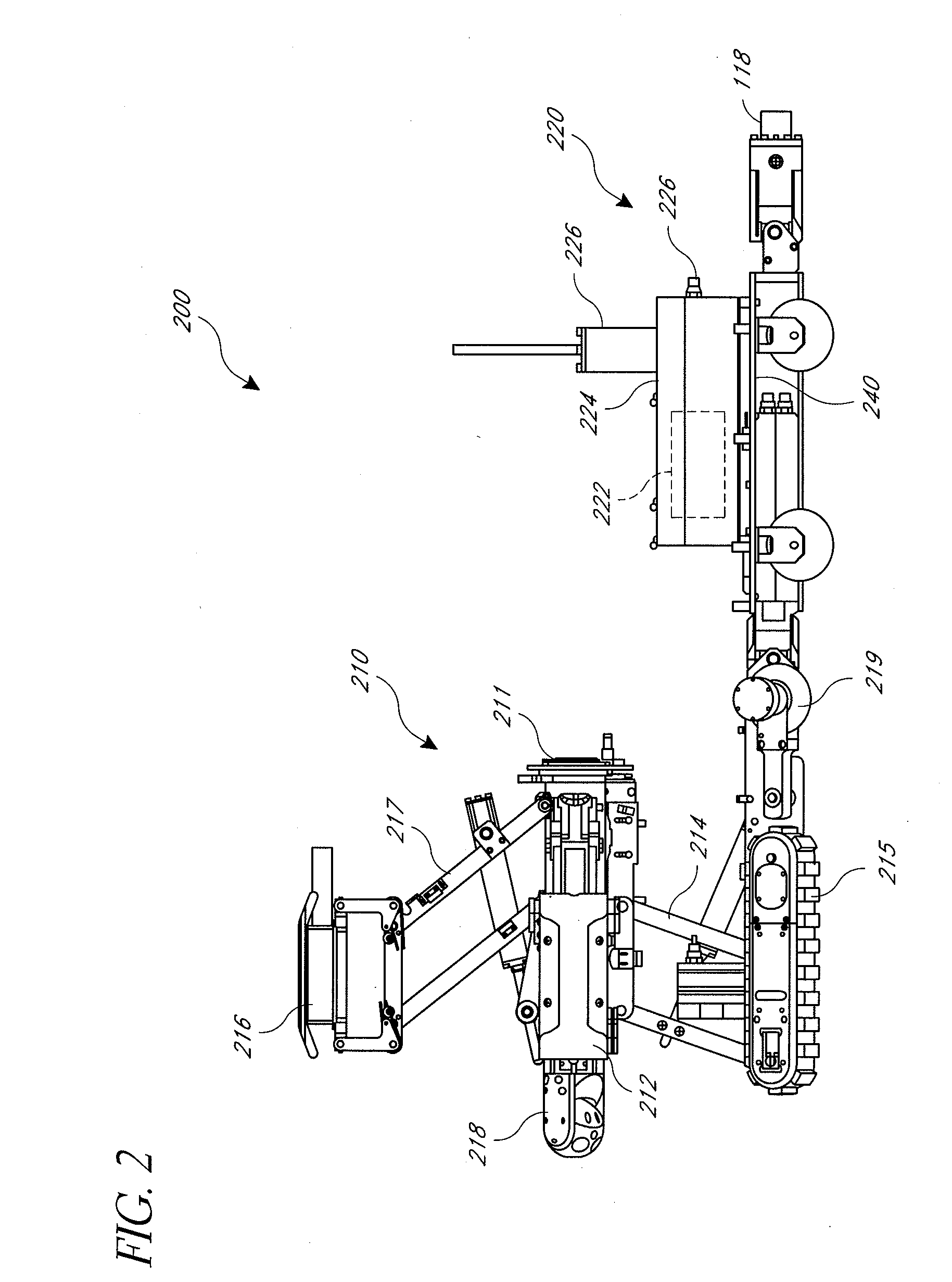
[0017]In certain embodiments, an antenna mount system is provided which is configured to hold a ground-penetrating radar (GPR) antenna in proximity to an inner surface of a pipe to be inspected while the GPR antenna is moved along the inner surface during inspection of the pipe. The system comprises a support structure configured to adjust a position of the GPR antenna in response to a force applied to the GPR antenna by the surface. In response to a drag or friction force between the surface and the GPR antenna, the support structure adjusts the position of the GPR antenna substantially along a direction of the drag or friction force. For example, where inspection of the pipe comprises orienting the GPR antenna relative to a longitudinal axis of the pipe and moving the GPR antenna in a first direction along the surface, a drag or friction force is applied by the surface to the GPR antenna in a second direction substantially opposite to the first direction. In response to the drag or friction force, the support structure adjusts the position of the GPR antenna substantially along the second direction. In certain such embodiments in which inspection of the surface further comprises maintaining the orientation of the GPR antenna relative to the longitudinal axis of the pipe and moving the GPR antenna in the second direction along the surface, a drag or friction force is applied by the surface to the GPR antenna in the first direction, and the support structure adjusts the position of the GPR antenna substantially along the first direction.
[0018]In certain embodiments, a method of acquiring underground pipe inspection data is provided. The method comprises providing a robot with one or more ground-penetrating radar (GPR) antennas. The method further comprises placing the one or more GPR antennas at corresponding first positions along the periphery of an inside surface of a pipe. The method further comprises obtaining inspection data using the one or more GPR antennas at the corresponding first positions as the robot travels in a first direction substantially along a longitudinal axis of the pipe being inspected. The method further comprises repositioning the one or more GPR antennas to be at corresponding second positions. The method further comprises obtaining inspection data using the one or more GPR antennas at the corresponding second positions as the robot travels in a second direction substantially along the longitudinal axis of the pipe being inspected, the second direction substantially opposite to the first direction.

Problems solved by technology

Due to the less well defined character of such features, GPR applicability is not always predictable on these projects and interpretation of the results depends on the specific site conditions and on the experience of the technical personnel.

Method used


Image

  • Apparatus and method for inspection of underground pipes
  • Apparatus and method for inspection of underground pipes
  • Apparatus and method for inspection of underground pipes

Examples


Embodiment Construction

[0031]Although several embodiments, examples, and illustrations are disclosed below, it will be understood by those of ordinary skill in the art that the invention described herein extends beyond the specifically disclosed embodiments, examples and illustrations and includes other uses of the invention and obvious modifications and equivalents thereof. Embodiments are described with reference to the accompanying figures, wherein like numerals refer to like elements throughout. The terminology used in the description presented herein is not intended to be interpreted in any limited or restrictive manner simply because it is being used in conjunction with a detailed description of certain specific embodiments. In addition, embodiments can comprise several novel features and no single feature is solely responsible for its desirable attributes or is essential to practicing the inventions herein described.

[0032]The various embodiments provide novel methods, systems and devices for electr...


PUM


Abstract

A system for inspecting an underground conduit from within comprises a data acquisition subsystem configured to be placed within the conduit and to move along at least a portion of the conduit to obtain data regarding the conduit. The system comprises a data storage subsystem configured to be placed within the conduit and to move along the conduit. The data storage subsystem receives and stores at least a portion of the data from the data acquisition subsystem for retrieval after the data acquisition subsystem has moved along the conduit.

Description

RELATED APPLICATIONS[0001]This application claims priority from, U.S. Provisional Patent Application No. 61 / 291,317, filed Dec. 30, 2009, the entirety of which is expressly incorporated by reference herein and made a part of the present specification.BACKGROUND[0002]1. Field of the Invention[0003]The present application generally relates to underground conduit inspection. More specifically, the present application relates to an improved underground conduit inspection system utilizing ground-penetrating radar.[0004]2. Description of the Related Art[0005]Ground-penetrating radar (GPR) is a real-time, non-destructive testing technique that can be used to locate targets embedded in concrete and to inspect the interior walls of concrete structures. GPR operates on the principle of transmission, reflection, and detection of short duration electromagnetic pulses from a transducer that is moved across the surface of the structure being analyzed.[0006]GPR utilizes high frequency radio waves ...

Claims


Application Information

Patent Timeline
Patent Type & Authority Applications(United States)
IPC IPC(8): G06F19/00G01S13/00
CPCF17D5/00F16L55/48G01B7/34G01B11/30G01B15/08G01B21/30G01M99/00G01D21/00G01N33/00
Inventor EKES, CSABANEDUCZA, BORISZLAV
Owner SEWERVUE TECH CORP
Learn More