Weighing apparatus

a technology of weighing apparatus and weighing plate, which is applied in the direction of weighing apparatus for continuous material flow, instruments, transportation and packaging, etc., can solve the problems of shortened weighing time and deteriorating weighing accuracy, so as to avoid a decrease in weighing accuracy

Inactive Publication Date: 2011-08-11
ISHIDA CO LTD
View PDF15 Cites 5 Cited by
  • Summary
  • Abstract
  • Description
  • Claims
  • Application Information

AI Technical Summary

Benefits of technology

[0004]The conveyor speed for the weighing conveyor is sometimes set too high in order to avoid double count errors. When the conveyor speed is high, the processing performance of the weighing device (i.e., the number of items that can be processed per unit of time) is improved. On the other hand, the time each item is placed on the weighing conveyor is shortened. Accordingly, the available time for weighing is also shortened so that the weighing accuracy deteriorates.
[0005]The present invention is contrived to solve these matters. More specifically, an object of the present invention is to obtain a weighing device able to avoid a loss in measurement precision caused by the conveyor speed being set too high.

Problems solved by technology

Accordingly, the available time for weighing is also shortened so that the weighing accuracy deteriorates.

Method used


Image

  • Weighing apparatus
  • Weighing apparatus
  • Weighing apparatus

Examples


1st embodiment

[0036]The following is a detailed description of a first embodiment of the present invention with reference to the drawings. The elements denoted by the same reference symbols in the different drawings are identical or corresponding elements.

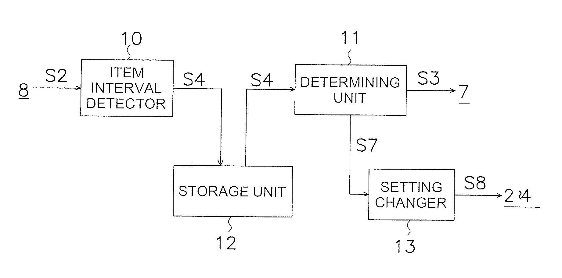
[0037]FIG. 1 is a view schematically showing the configuration of the weighing apparatus 1 according to an embodiment of the present invention. The weighing apparatus 1 includes a take-in conveyor 2, a weighing conveyor 3 (a conveying unit), a sorting conveyor 4, a weighing unit 5, a control unit 6, a display unit 7 (a presenting unit), and photosensor 8. The weighing unit 5 is a load cell and the like. The weighing unit 5 measures the weight of the items Q conveyed on the weighing conveyor 3. The control unit 6 is a computer and the like. The display unit 7 is a liquid crystal display device with an integrated touch screen and the like. The photosensor 8 is configured to detect the items Q passed from the take-in conveyor 2 to the weighing conv...

2nd embodiment

[0061]The following is a detailed description of a second embodiment of the present invention with reference to the drawings. The elements denoted by the same reference symbols in the different drawings are identical or corresponding elements.

Overall Configuration

[0062]FIG. 8 is a view schematically showing the configuration of the weighing apparatus 100 in an embodiment of the present invention. The weighing apparatus 100 includes a take-in conveyor 20, a weighing conveyor 30 (a conveying unit), a sorting conveyor 40, a weighing unit 50, a control unit 60, a display unit 70 (a presenting unit), and a photosensor 80.

[0063]The take-in conveyor 20 is disposed downstream from a transport conveyor 90 which is an upstream device. A weighing conveyor 30 and a sorting conveyor 40 are disposed downstream from a take-in conveyor 20. A plurality of items Q is supplied intermittently from the transport conveyor 90 to the take-in conveyor 20. Similarly, a plurality of items Q is supplied interm...


PUM


Abstract

A weighing apparatus includes a conveying unit, a weighing unit, a detecting unit, a first storing unit and a presenting unit. The conveying unit is configured to convey an item. The weighing unit is configured to measure a weight of the item conveyed on the conveying unit. The detecting unit is configured to detect an item interval related to a distance between a plurality of items supplied to the conveying unit. The first storing unit is configured to store a plurality of item intervals acquired by the detecting unit during a predetermined period of time. The presenting unit is configured to provide, based on the item intervals stored in the first storing unit, guidance related to a change in an item conveying speed of the conveying unit.

Description

CROSS-REFERENCE TO RELATED APPLICATIONS[0001]This national phase application claims priority to Japanese Patent Application No. 2008-259128 filed on Oct. 4, 2008. The entire disclosure of Japanese Patent Application Nos. 2008-259128 is hereby incorporated herein by reference.TECHNICAL FIELD[0002]The present invention relates to a weighing apparatus.BACKGROUND ART[0003]In a weighing apparatus, as disclosed, for example, in Japanese Laid-open Patent Publication No. 61-14047, items are intermittently supplied from an upstream device to a weighing conveyor. Here, when a plurality of items is put at a time on the weighing conveyor, accurate weighing cannot be performed (so-called double count errors). Therefore, the conveyor speed for the weighing conveyor is set in accordance with a distance interval between the supplied items (item interval).SUMMARY OF THE INVENTION[0004]The conveyor speed for the weighing conveyor is sometimes set too high in order to avoid double count errors. When t...

Claims


Application Information

Patent Timeline
Patent Type & Authority Applications(United States)
IPC IPC(8): G06F17/30
CPCG01G11/12B65G43/08
Inventor SAKAGAMI, YOSHIAKITAKAHASHI, ATSUSHI
Owner ISHIDA CO LTD
Why Eureka
Try Eureka