
Medicine packaging apparatus

a technology of medicine packaging and packaging apparatus, which is applied in the directions of packaging, transportation and packaging, packaging, etc., can solve the problems of affecting the downsizing affecting the production efficiency of the medicine packaging apparatus, and unable to prevent the generation of wrinkles

Active Publication Date: 2011-08-18
YUYAMA MFG CO LTD
View PDF13 Cites 10 Cited by
  • Summary
  • Abstract
  • Description
  • Claims
  • Application Information

AI Technical Summary

Benefits of technology

[0032]In the medicine packaging apparatus of the present invention, the unfolding guide is provided with the pair of unfolding guide surfaces which are convex curved surfaces, and the contact start position with the package sheet of the unfolding guide surface located on the outer side of the curve in the conveying direction of the package sheet is set on the upstream side in the conveying direction of the package sheet of the contact start position with the package sheet of the unfolding guide surface located on the inner side of the curve. Thus, the printing section, the curvature guide, the unfolding guide, the medicine introducing section, and the printing section are placed in the vicinity of each other, and the distance from the printing section to the heat sealing section can be reduced without generating the wrinkles on the package sheet. The reduced distance from the printing section to the heat sealing section makes it possible to eliminate a waste of the package sheet due to the roll replacement and the like so as to achieve the running cost reduction while achieving the downsizing of the device. Moreover, the vibration applying mechanism for applying the vibration to the unfolding guide and the hopper is provided, so that the residual medicine in the hopper can be prevented without causing the displeasure and the false detection of the failure.BEST MODES FOR CARRYING OUT THE INVENTIONFirst Embodiment
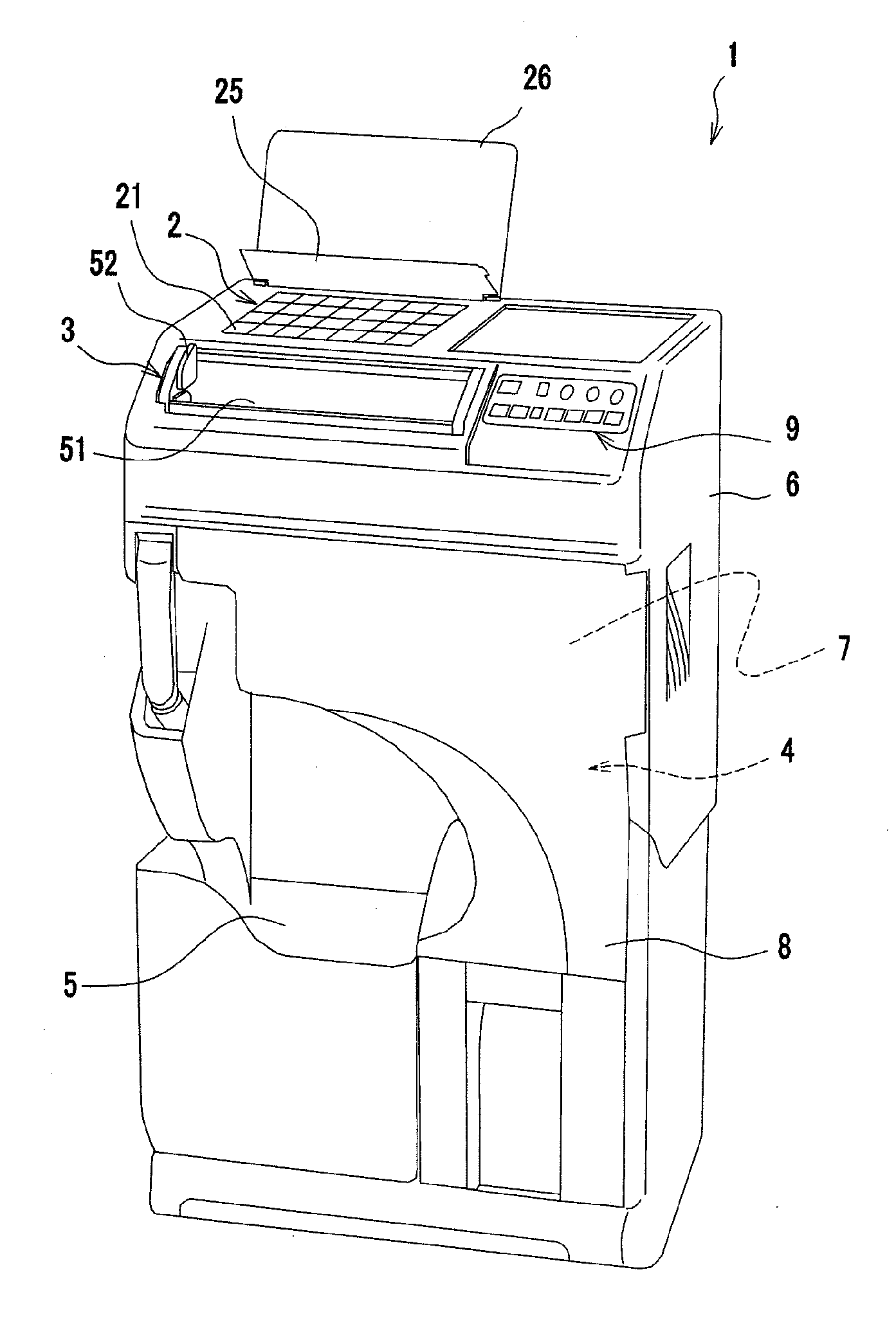
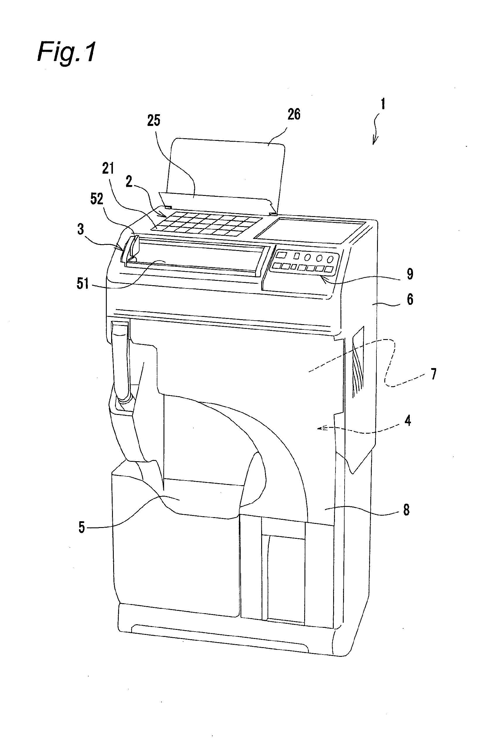
[0033]FIG. 1 shows a medicine packaging apparatus 1 according to an embodiment of the present invention.
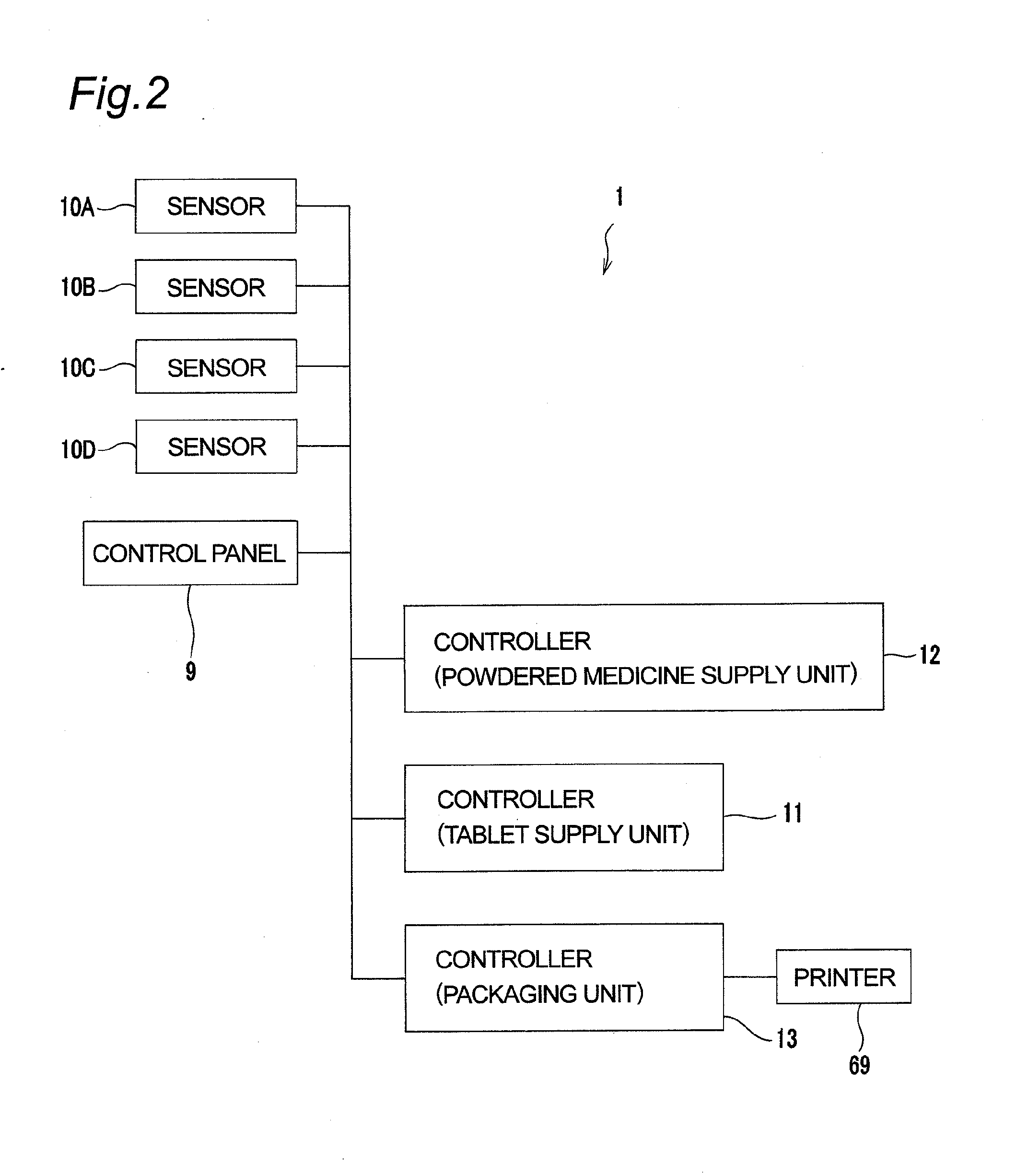
[0035]The medicine packaging apparatus 1 includes a tablet supply unit 2, a powdered medicine supply unit 3, a packaging unit 4, and a medicine discharge section 5 from which packaged medicine is discharged. The tablet supply unit 2 and the powdered medicine supply unit 3 are provided on the upper surface side of a housing 6. Meanwhile, the packaging unit 4 is arranged in housing space 7 inside the housing 6. An opening on the front surface of the housing 6 is openably covered by an openable and closable cover 8 in the shape of a single swinging door except for the medicine discharge section 5. When opening this cover 8, an operator can access the packaging unit 4 inside the housing space 7. The form of the cover 8 is not particularly limited, and another form such as a double leaf form may be employed. A control panel 9 is provided on the upper surface of the housing 6. Also with reference to FIG. 2, the operation of the tablet supply unit 2, the powdered medicine supply unit 3 and the packaging unit 4 are controlled by controllers 11, 12, 13 based on the inputs from the control panel 9, the inputs from various sensors 10A to 10D, and the prescription information inputted from the outside. In the present embodiment, the tablet supply unit 2 is controlled by the controller 11, the powdered medicine supply unit 3 is controlled by the controller 12, and the packaging unit 4 is controlled by the controller 13. However, two or more units among the tablet supply unit 2, the powdered medicine supply unit 3, and the packaging unit 4 may be controlled by a common controller.
[0037]In the following, the tablet supply unit 2 is described with reference to FIGS. 3A to 5. First, with reference to FIGS. 3A, 3B, and 5, the tablet supply unit 2 includes a fixed tablet housing section 22 in which a plurality of tablet housing chambers 21 is provided in matrix form (and which constitutes part of the upper surface side of the housing 6 in the present embodiment) and a tablet discharging section 23 that automatically and sequentially takes out tablets for each dose supplied by manual distribution into the respective tablet housing chamber 21, and supplies the tablets to the packaging unit 4.
[0038]With reference to FIGS. 3A, 3B, and 4, the tablet housing section 22 in the present embodiment is provided with a total of 28 tablet housing chambers 21 in identical shape in four rows in the anteroposterior direction (row direction) and seven columns in the lateral direction (column direction). Both the upper and lower ends of the respective tablet housing chambers 21 are open. An upper end opening 21a functions as an opening for the operator to manually feed the tablets into the tablet housing chambers 21. A lower end opening 21b functions as an opening through which the tablets housed inside the tablet housing chambers 21 pass to the tablet discharging section 23.
[0039]With reference to FIG. 4, the tablet housing section 22 includes a closing cover 25 generally in sheet shape or plate shape and a protection cover 26 also having generally sheet shape or plate shape. The closing cover 25 and the protection cover 26 are rotatably fixed to the upper surface of the tablet housing section 22. When the protection cover 26 is at an open position, the closing cover 25 can be set to either an open position where the closing cover is receded from the tablet housing section 22 or to a closed position where the closing cover is placed on the tablet housing section 22 to close the upper end openings 21a of the seven tablet housing chambers 21 constituting the rearmost-side one row.

Problems solved by technology

In other words, in the roll replacement and the like, a length of the package sheet from the printing section to the heat sealing section (length generally equivalent to 5 to 6 packages) functions only for the routing, i.e., the length is not used for medicine packaging and therefore should be discarded, which is not desirable in view of cost.
Moreover, the long path of the package sheet from the printing section to the heat sealing section hinders downsizing of the medicine packaging apparatus.
However, merely shortening the path cannot prevent generation of wrinkles on the package sheet in a portion of the heat sealing section.
Such wrinkles 1105 result in poor airtightness due to sealing failure and thereby cause mixture (contamination) of the medicine between adjacent prescriptions.

Method used


Image

  • Medicine packaging apparatus
  • Medicine packaging apparatus
  • Medicine packaging apparatus

Examples


first embodiment

[0033]FIG. 1 shows a medicine packaging apparatus 1 according to an embodiment of the present invention.

[0034](Entire Configuration)

[0035]The medicine packaging apparatus 1 includes a tablet supply unit 2, a powdered medicine supply unit 3, a packaging unit 4, and a medicine discharge section 5 from which packaged medicine is discharged. The tablet supply unit 2 and the powdered medicine supply unit 3 are provided on the upper surface side of a housing 6. Meanwhile, the packaging unit 4 is arranged in housing space 7 inside the housing 6. An opening on the front surface of the housing 6 is openably covered by an openable and closable cover 8 in the shape of a single swinging door except for the medicine discharge section 5. When opening this cover 8, an operator can access the packaging unit 4 inside the housing space 7. The form of the cover 8 is not particularly limited, and another form such as a double leaf form may be employed. A control panel 9 is provided on the upper surface...

second embodiment

[0075]A second embodiment of the present invention shown in FIGS. 23 to 29 is different from the first embodiment only in the configuration of the unfolding guide 65.

[0076]As most clearly shown in FIGS. 23, 25, and 27, in the present embodiment, the shoulder sections 99a, 99b of the unfolding guide surfaces 95a, 95b are wide and an area of the top surfaces 96a, 96b is correspondingly narrow. The unfolding guide surfaces 95a, 95b excluding the shoulder sections 99a, 99b are smooth curved surfaces without concave as a whole, and have long and narrow flat sections 109a, 109b extending along the rear end edges 97a, 97b.

[0077]As in the first embodiment, as seen from the conveying direction A of the package sheet 61, the outline of the unfolding guide surfaces 95a, 95b excluding the flat sections 109a, 109b is a convex curve, and the distance between the pair of unfolding guide surfaces 95a, 95b is widened as they are farther away from the main ridge 94. As seen from the direction orthog...

third embodiment

[0088]In the following, a third embodiment of the present invention is described with reference to FIGS. 30 to 38. The third embodiment is different from the first embodiment only in the packaging unit 4 of the medicine packaging apparatus 1. In the third embodiment, instead of the curvature guide rollers 81A, 81B, a fixed guide rod 181 is placed (see FIG. 12 in particular). More specifically, the guide rod 181 curves the conveying direction of the package sheet 61, which travels from the back side to the front side along with the side holding section 71b, toward the front side of the front holding section 71a, and guides the package sheet 61 to diagonally downward as seen from the front side of the front holding section 71a. The guide rod 181 extends from the front holding section 71a to the direction in which the front holding section 71a stretches and also to the direction slantingly downward. The direction in which a side edge of the guide rod 181 extends on the downstream side ...


PUM

PropertyMeasurementUnit
Areaaaaaaaaaaa
Distanceaaaaaaaaaa

Abstract

In a medicine packaging apparatus, a distance from a printing section to a heat sealing section is reduced without generating wrinkles on a package sheet. An unfolding guide 65 for unfolding and opening a package sheet 61 provided in a packaging unit 4 includes a main ridge 94 extending along with a crease of the package sheet 61 and a pair of unfolding guide surfaces 95a, 95b which are convex curved surfaces stretching from the main ridge 94. A contact start position 100a with the package sheet 61 of the unfolding guide surface 95a on the outer side of a curve in the conveying direction A relative to the main ridge 94 is located on an upstream side in the conveying direction A of the package sheet 61 of a contact start position 100b with the package sheet 61 of the unfolding guide surface 95b located on the inner side of the curve relative to the main ridge 94.

Description

TECHNICAL FIELD[0001]The present invention relates to a medicine packaging apparatus for packaging medicine such as a tablet including a capsule tablet and powdered medicine.BACKGROUND ART[0002]Various medicine packaging apparatuses have been provided which prepare continuous medicine bags or dose packages by packaging medicine such as a tablet and powdered medicine per dose (as one medicine bags) based on prescriptions. Some of these devices use package sheet rolls on which a long and narrow package sheet previously folded into two in the longitudinal direction is wound. Generally, in a packaging section of this kind of medicine packaging apparatus, a package sheet is fed from the roll, and required information is printed thereon by a printing section. The package sheet is then unfolded from the folded state to be opened, and a nozzle section of a hopper is inserted into the opening to introduce one dose of the medicine. Next, the package sheet is sealed (heat-sealed) in a heat sea...

Claims


Application Information

Patent Timeline
IPC IPC(8): B65B61/26B65B1/30
CPCB65B1/22B65B1/30B65B5/103B65B61/025B65B43/04B65B51/28B65B9/067B65B9/06B65B39/00B65B51/16B65B61/02
Inventor YUYAMA, SHOJITAKEDA, NAKAJI
Owner YUYAMA MFG CO LTD
Learn More