Guide device

a technology of guide device and guide rod, which is applied in the direction of lighting and heating apparatus, domestic heating details, domestic heating, etc., can solve the problems of high material input, comparatively complex guide and side grates, and large input of materials

Inactive Publication Date: 2011-08-18
PAUL HETTICH
View PDF19 Cites 0 Cited by
  • Summary
  • Abstract
  • Description
  • Claims
  • Application Information

AI Technical Summary

Benefits of technology

The present disclosure provides for a guide apparatus which is arranged in a simple way and has a low need for energy.
In accordance with the present disclosure, the guide apparatus includes a baking support which is supported on the horizontal bars of a side grate or a side wall. The apparatus includes at least one holding means which engages beneath the horizontal bar on which the baking support is supported, in order to form a tilt protection mechanism. As a result, the side grate can be provided with a considerably lower number of horizontal bars because the horizontal bar on which the baking support rests simultaneously forms the support and the tilt protection mechanism. As a result of the engagement beneath the horizontal bar, downward tilting is prevented when withdrawing the baking support. The baking-supports tend to tilt downwardly as a result of gravity but the horizontal bar has been engaged underneath and forms a stop for the holding means. By reducing the number of bars on the opposite sides of the side grate, the input of material is reduced, so that the energy requirements of a respective guide apparatus in a baking oven will be reduced. Moreover, pull-out guides can be mounted more easily on the side grate due to the larger distance of the horizontal bars. Further savings in energy and material can be achieved by omitting the vertical bars of the side grate and fixing the horizontal bars in the side wall in a positive, non-positive or firmly bonded way.
In a further embodiment according to the present disclosure, the at least one holding means is arranged in a rear section of the baking support in the pull-out direction. Tilting of the baking support needs to be prevented especially when withdrawing the baking support from the oven, since there will be a tilting motion as a result of gravity. Locating the holding means in the rear section may be necessary, and tilting can be reduced to this area. It is also possible to provide the holding means with a longer configuration, for example, more than half or 70% of the length of the lateral edge of the baking support, so that better guidance of the baking support on the horizontal bar is ensured.
For simple production, the at least one holding means can be made of a bent wire. The wire can be led through an opening on the baking support for fixing. The holding means can thus be retrofitted in a very simple way.

Problems solved by technology

The guidance of the support floor via the pull-out guide and the mounting on the side grates is comparatively complex and requires numerous components.
It is disadvantageous in this construction that the two horizontal bars mean a high input of material because several baking levels are provided in the side grate.

Method used


Image

  • Guide device
  • Guide device
  • Guide device

Examples


Embodiment Construction

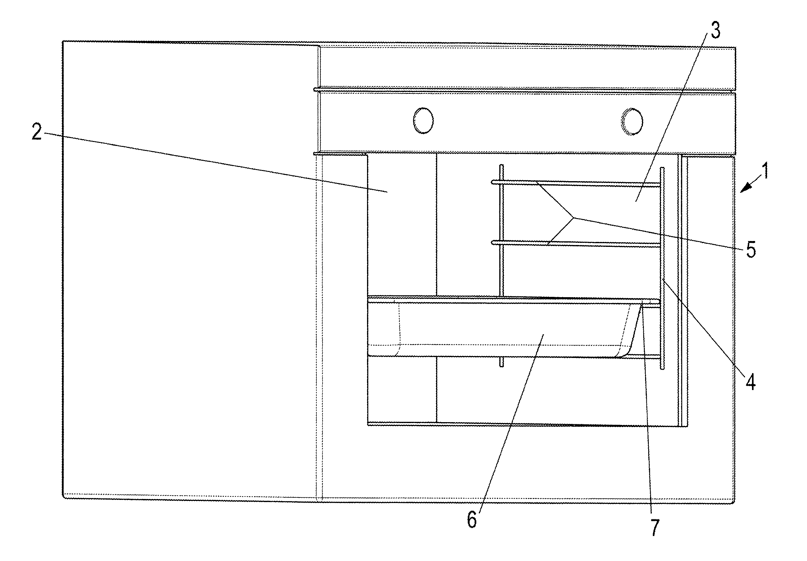
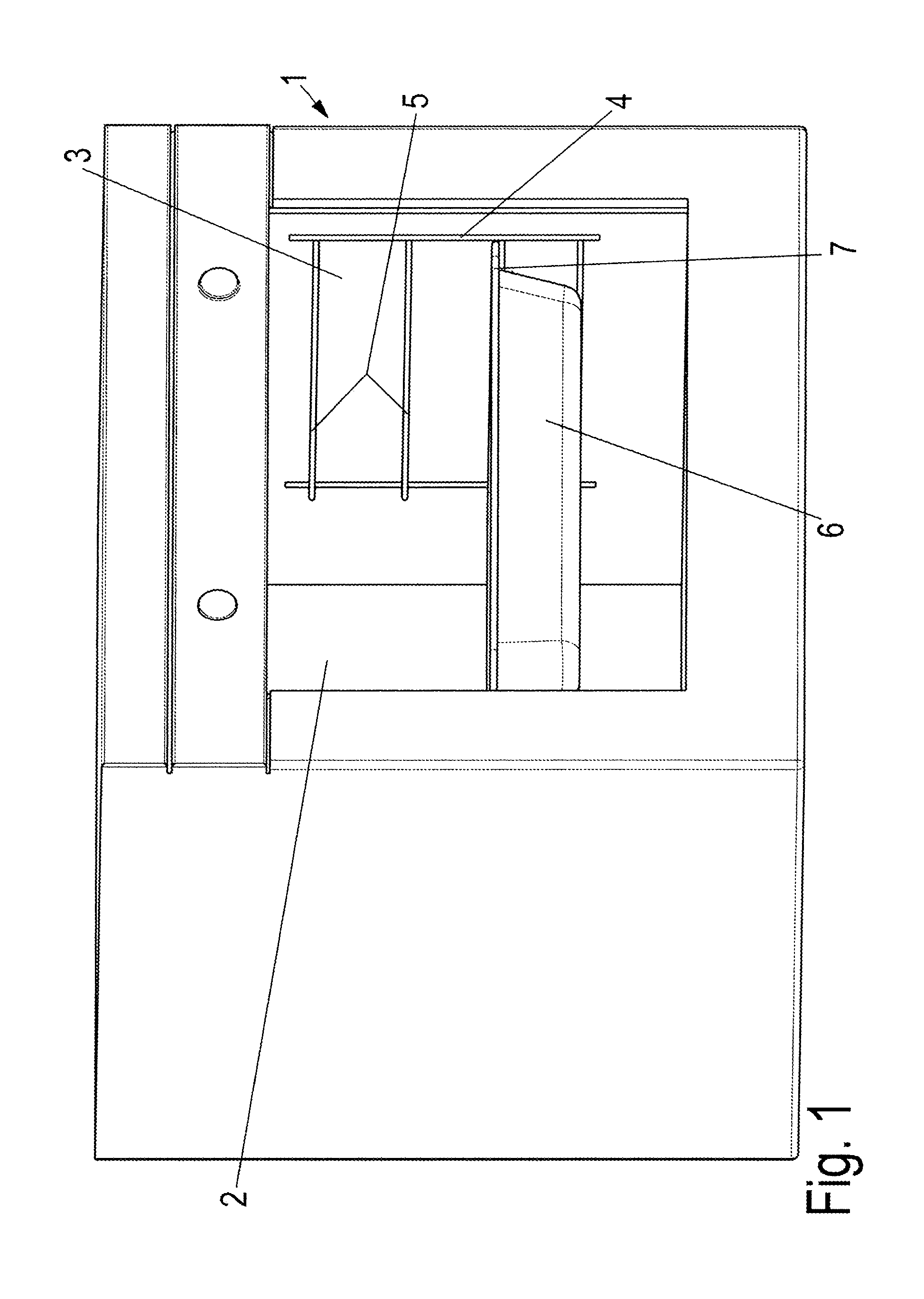
A baking oven 1 comprises a heatable interior space 2 which comprises a side grate 4, of a guide apparatus, according to the present disclosure, on opposite side walls 3. The side grate 4 is fixed via fastening means (not shown) to the side wall 3 and comprises a plurality of horizontal bars 5 which are fixed at opposite ends to vertical bars. Each horizontal bar 5 forms a baking level and is used for supporting a baking support 6 which is arranged or configured, for example, as a baking tray and which baking support 6 comprises a laterally protruding edge 7.

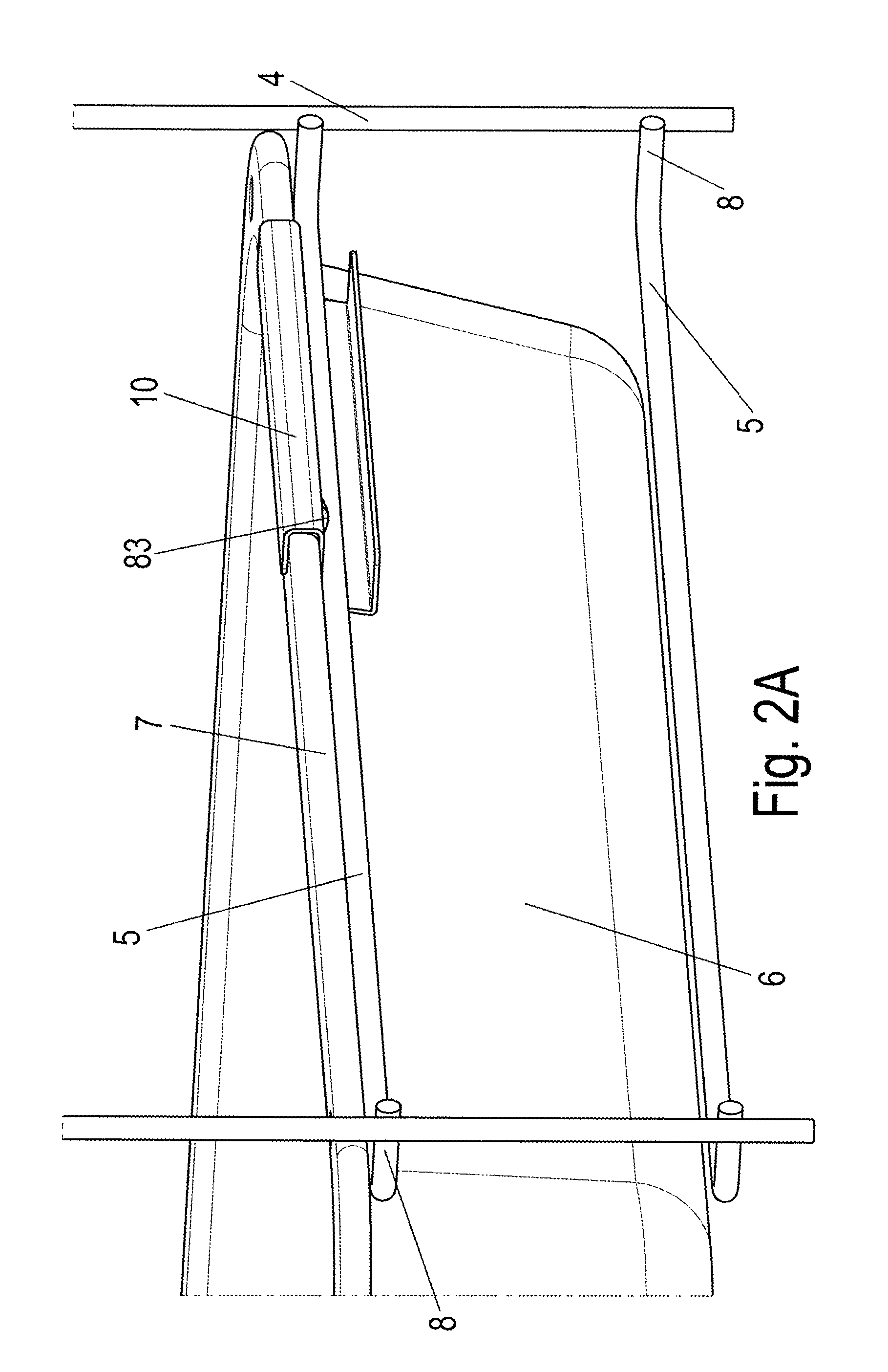
As is shown in an embodiment of the present disclosure in FIGS. 2A and 2B, the laterally protruding edge 7 of the baking support 6 is provided with a holding means 10 in the form of a strip-like bent sheet in a rear region adjacent to a rear wall of the baking oven 1. The holding means or sheet 10 is arranged in a virtually S-shaped manner in its cross section. The holding means 10 comprises a first U-shaped receiver which is de...


PUM


Abstract

A guide apparatus for a baking oven. The guide apparatus includes a baking support including a projecting edge on opposite sides of the baking support. Further included is a side wall of the oven and a plurality of horizontal bars mounted on the side wall. The horizontal bars form at least one baking level and support the projecting edges of the baking support. Also included is at least one holding means provided on the baking support, which holding means engages beneath one of the plurality of horizontal bars and forms a tilt protection mechanism.

Description

BACKGROUND AND SUMMARYThe present disclosure relates to a guide apparatus, particularly a guide apparatus for use in a baking oven. A baking support is supported on its opposite sides by a projecting section configured to be placed on a horizontal bar of a lateral grate or on a side wall of the baking oven. The apparatus includes a plurality of horizontal bars located at vertical distances on the respective side grate or on the respective side wall to form a plurality of baking levels.A support floor of a kitchen appliance is known from DE 20 2004 005475, which support floor is fixed on opposite sides to a running rail of a pull-out guide. The pull-out guide is held on a side grate and is secured there against tilting in the extended position. The guidance of the support floor via the pull-out guide and the mounting on the side grates is comparatively complex and requires numerous components. Moreover, the metallic components have a high thermal storage capacity, so that the operati...

Claims


Application Information

Patent Timeline
IPC IPC(8): F24C15/16
CPCF24C15/16
Inventor TUNSCHEL, HORSTBUDDE, SVEN
Owner PAUL HETTICH
Why Eureka
Try Eureka