Relief manufacturing apparatus and relief manufacturing method

Active Publication Date: 2011-08-18
FUJIFILM CORP
View PDF11 Cites 3 Cited by
  • Summary
  • Abstract
  • Description
  • Claims
  • Application Information

AI Technical Summary

Benefits of technology

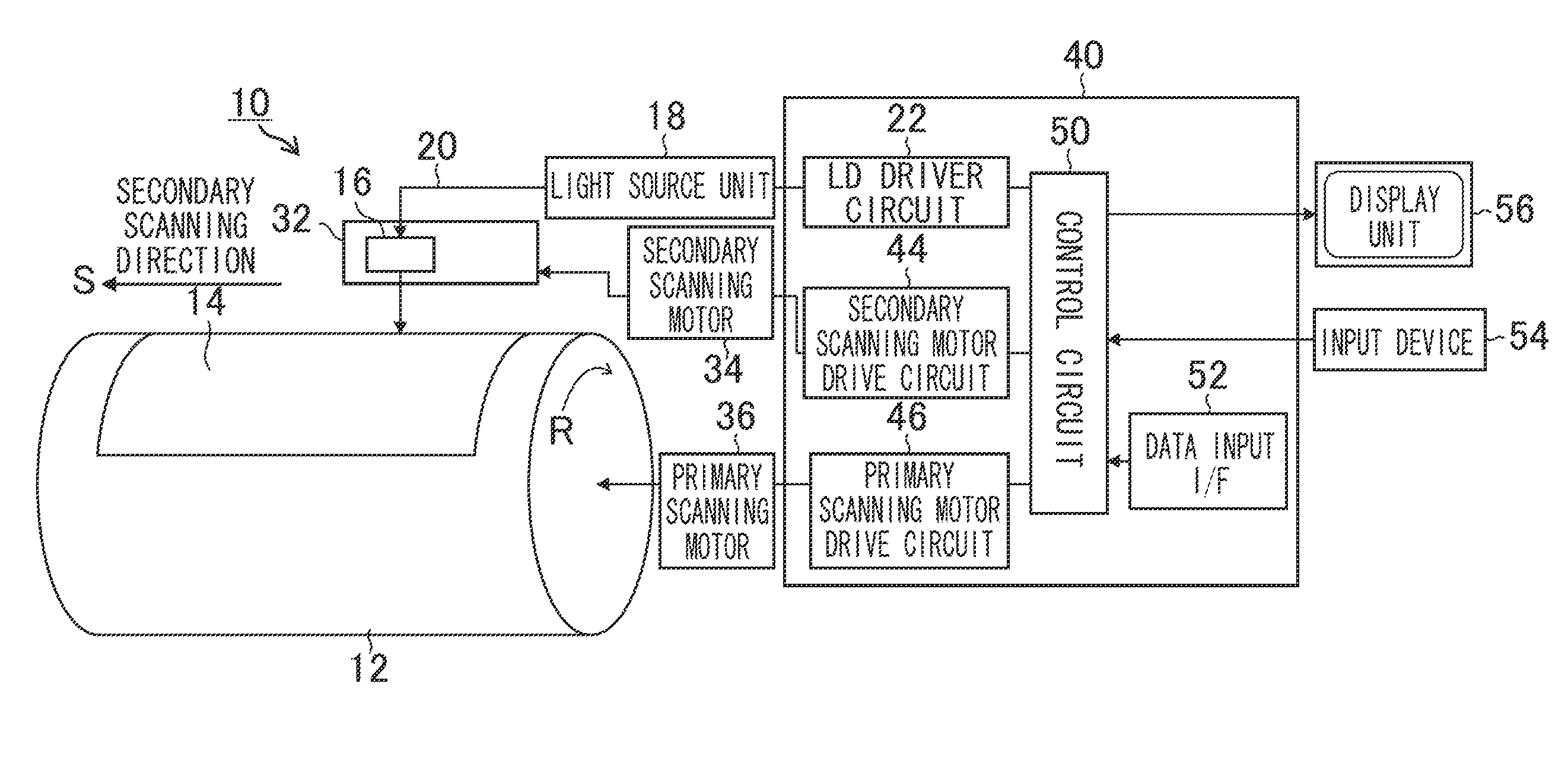
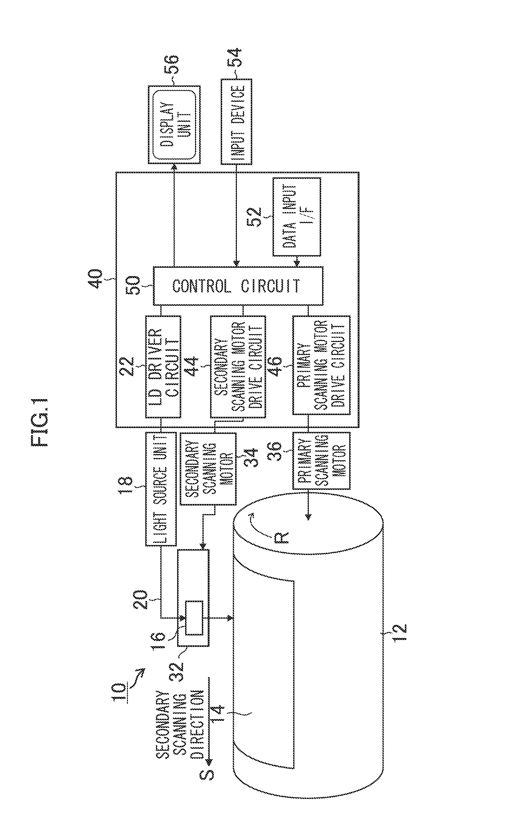
[0011]In this way, after forming of the initial inclined face having a smaller inclination angle by irradiating the laser beam, control is performed to steepen the inclined face. Accordingly, a microscopic and steep inclined face can easily be formed. That is, when the desired inclination angle of the inclined face is great, the conventional technique forming the desired inclined face by a single scanning requires a significantly great laser beam power; thus, part of or all of a top face which should remain unchanged may be removed by thermal effects. According to the presently disclosed subject matter, however, the forming of the initial inclined face having a small inclination angle and the steepening of the inclined face are separately performed; thus, when a microscopic engraving is needed, also, the inclined face having a great inclination angle can easily be formed while ensuring that the necessary top face remains unchanged. According to the conventional technique forming the inclined face of a staircase shape through on / off switching of a laser beam, the number of steps of the staircase must be enlarged to smoothen the inclination of the staircase-shaped inclined face. According to the presently disclosed subject matter, however, control is performed so that the inclination angle of the inclined face is enlarged. Thus, the microscopic and steep inclined face can easily be formed while the number of times of laser beam irradiation is not enlarged so much.
[0014]According to an aspect of the presently disclosed subject matter, the control device irradiates a laser beam by a single scanning on both the first initial inclined face and the second initial inclined face and thereby enlarges the inclination of the first initial inclined face and the inclination of the second initial inclined face from the second inclination angle to the first inclination angle.
[0015]In this way, both the first inclined face and the second inclined face are steepened by a single scanning and thus the inclined face can be quickly steepened to the desired inclination angle.
[0018]In this way, in enlarging the inclination angle, the bottom face is not engraved and thus the accuracy of the inclined face is securely prevented from being degraded by heat of the laser beam irradiated on the bottom face.
[0033]According to the presently disclosed subject matter, a microscopic and steep inclined face can easily be formed.

Problems solved by technology

When a steep inclined face is formed by a single laser beam irradiation, a significantly great laser beam power must be used; in this case, there may arise a problem that an area which should remain unchanged is thermally affected and removed.
This problem is especially remarkable when the desired width of the top face 91 is small.
Accordingly, it is practically not easy to form a microscopic inclined face having a great inclination angle.

Method used


Image

  • Relief manufacturing apparatus and relief manufacturing method
  • Relief manufacturing apparatus and relief manufacturing method
  • Relief manufacturing apparatus and relief manufacturing method

Examples


first embodiment

[0086]First, the presently disclosed subject matter will be described.

[0087]FIG. 7 is a view for explaining the basic principle of engraving by laser beam. This view illustrates a case in which an inclined face 82 having a desired inclination angle θd is formed using a single laser beam 80 by a single beam scanning. In a case in which the desired inclination angle θd is small, that is, in a case in which a gradually inclined face 82 is formed, when the inclined face 82 is formed by a single beam scanning, also, an edge 83 (ridge section) neighboring the inclined face 82 of a top face 81 can be accurately formed.

[0088]In a case in which the desired inclination angle θd is great, that is, in a case in which a steep inclined face 82 is formed, the inclined face 82 having the desired inclination angle θd is, as illustrated in FIG. 8, formed by multiple beam scannings (in this example, three scannings).

[0089]More specifically, the control circuit 50 acquires the desired inclination angle...

second embodiment

[0107]A second embodiment according to the presently disclosed subject matter will be described in detail.

[0108]FIG. 16A is a plan view illustrating an exemplary relief pattern 85 having a square point-like top face 81 (halftone dot). FIG. 16B is a cross-sectional view of the relief pattern 85 along the line B-B in a primary scanning direction R of FIG. 16A. The relief pattern 85 of this example has inclined faces 82e and 82f which incline towards the outside of a top face 81 while having the top face 81 therebetween.

[0109]Firstly, a first example of exposure control for forming the relief pattern 85 illustrated in FIGS. 16A and 16B will be described with reference to the explanatory views of FIGS. 17A and 17B.

[0110]FIG. 17A illustrates a plate material 14 after a first beam scanning. FIG. 17B illustrates the plate material 14 after a second beam scanning. Here, the beam scanning is performed along the line B-B of FIG. 16A.

[0111]In the engraving signal generation (step S108 of FIG. ...

third embodiment

[0120]A third embodiment according to the presently disclosed subject matter will be described below in detail.

[0121]In the first and second embodiments, exposure control in a primary scanning direction has been described. In the present embodiment, exposure control in a secondary scanning direction will be described. Here, the forming of the inclined faces in a primary scanning direction can be performed by the method described in the first embodiment or the second embodiment.

[0122]FIG. 19A is a plan view illustrating an exemplary relief pattern 85 having a square point-like top face 81 (halftone dot). FIG. 19B is a cross-sectional view of the relief pattern 85 along the line B-B in a secondary scanning direction S of FIG. 19A. Referring to FIG. 19B, reference numeral 241 designates the surface of the plate material 14 after a first exposure (laser beam); reference numeral 242 designates the surface of the plate material 14 after a second exposure; and reference numeral 243 designa...


PUM

PropertyMeasurementUnit
Angleaaaaaaaaaa
Poweraaaaaaaaaa
Areaaaaaaaaaaa

Abstract

A relief manufacturing apparatus includes: a laser beam irradiating device configured to irradiate laser beam on an engraving material; a scanning device configured to move at least one of the engraving material and the laser beam irradiating device; a numerical value acquiring device configured to acquire a numerical value including a first inclination angle indicating inclination of the inclined face of the relief; a control device configured to control the scanning device and the laser beam irradiating device so that the laser beam is irradiated on a surface of the engraving material to form an initial inclined face having a second inclination angle smaller than the first inclination angle and thereafter the laser beam is irradiated on the initial inclined face to enlarge the inclination of the inclined face from the second inclination angle to the first inclination angle.

Description

BACKGROUND OF THE INVENTION[0001]1. Field of the Invention[0002]The presently disclosed subject matter relates to relief manufacturing apparatuses and relief manufacturing methods which perform engraving using a laser beam to manufacture a relief, and more particularly to a relief manufacturing apparatus and a relief manufacturing method which can easily form a microscopic and steep inclined face.[0003]2. Description of the Related Art[0004]A method is known in which engraving is performed by irradiating a laser beam on the surface of an engraving material to manufacture a relief having a concave and convex relief pattern; while a top face (for example, halftone dot) used as a printing area remains unchanged, an area surrounding the top face is removed by the irradiating laser beam, whereby a printing plate is manufactured.[0005]Japanese Patent No. 3556204 discloses a method which performs on / off switching of the laser beam to repeatedly irradiate the laser beam plural times on the ...

Claims


Application Information

Patent Timeline
IPC IPC(8): B23K26/00B41C1/05
CPCB23K26/0823B41C1/05B23K26/38
Inventor NORIMATSU, MASASHIMIYAGAWA, ICHIROUSHIMAZAKI, OSAMU
Owner FUJIFILM CORP
Why Eureka
Try Eureka