Rotary Welding Torch

a welding torch and rotary technology, applied in the direction of arc welding apparatus, cooled electrode holders, electrode holders, etc., can solve the problems of cable (fixed or rotary), adversely affecting the welding process and the quality of the final weld, and the welding pool

Active Publication Date: 2011-08-18
CENKO ARBEN
View PDF13 Cites 10 Cited by
  • Summary
  • Abstract
  • Description
  • Claims
  • Application Information

AI Technical Summary

Benefits of technology

[0030]The rotary welding torch may further comprise one or more wire guide assemblies which provide a supply of electrode wire to the

Problems solved by technology

The electrical arc may cause the work piece to melt thereby creating a weld pool.
This becomes a problem, as the cables (whether fixed or rotary), are subjected to severe mechanical wear du

Method used


Image

  • Rotary Welding Torch
  • Rotary Welding Torch
  • Rotary Welding Torch

Examples


first embodiment

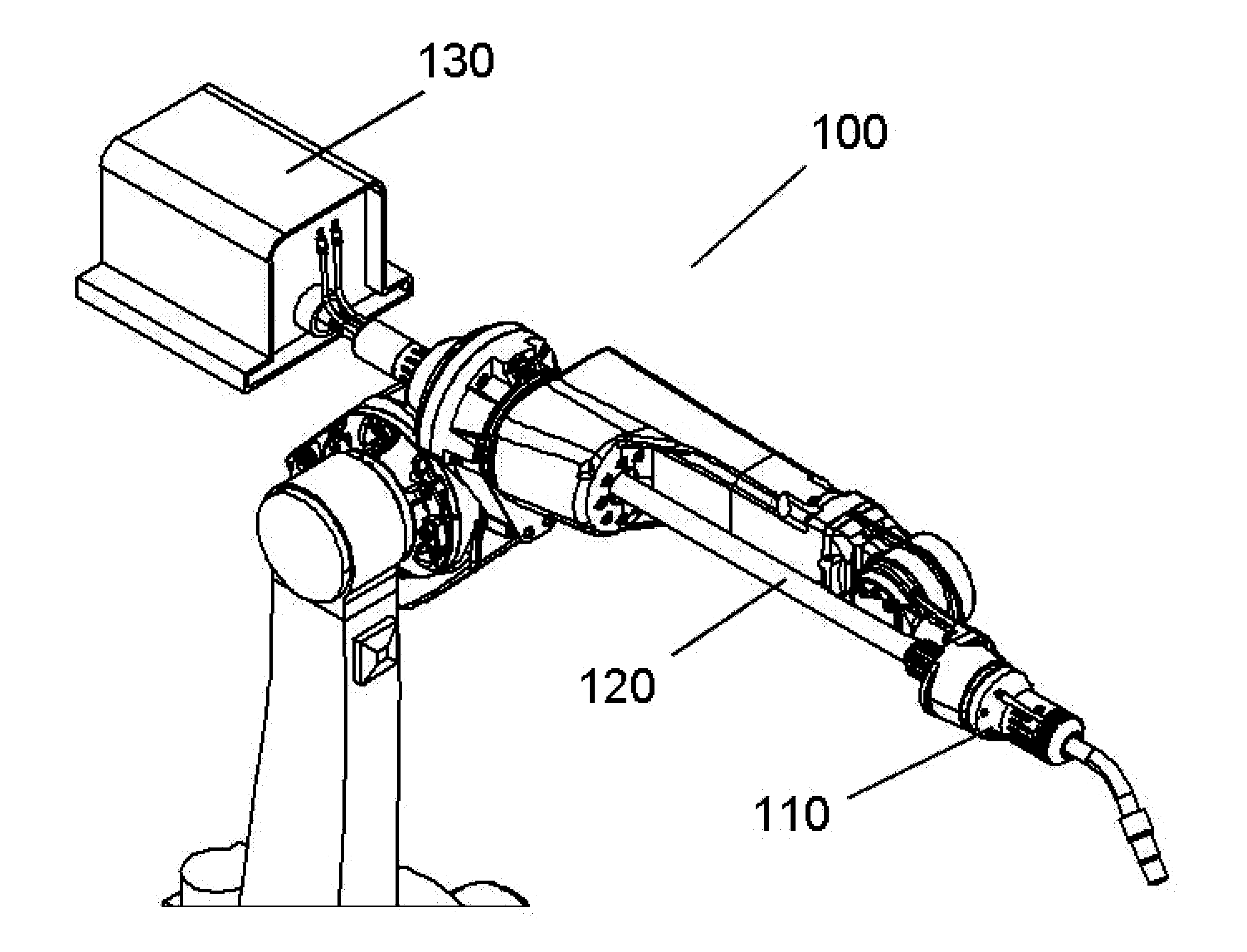
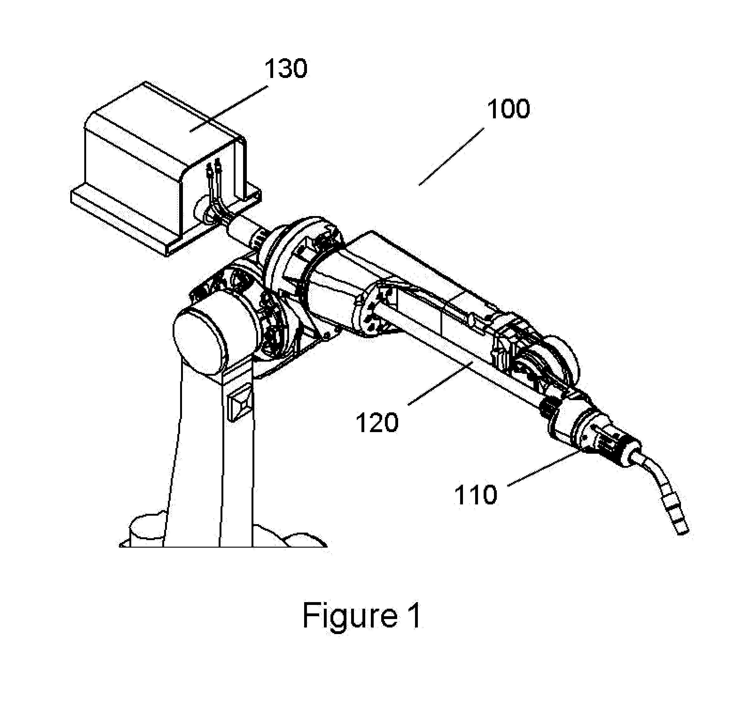
[0039]In the present disclosure there is provided a MIG robotic welding torch. The MIG robotic welding torch comprises a rotary welding assembly, a supply conduit, a source of electrode wire, a coolant source, an inert gas source and a power source. The MIG robotic welding torch provides for endless rotation in the clockwise or counterclockwise direction during use. A depiction of a MIG welding torch 100 in accordance with the present disclosure is depicted in FIG. 1. The MIG welding torch generally comprises a rotary welding assembly 110, a supply conduit 120, an inert gas source and a power source. The rotary welding torch may additionally comprise a source of electrode / filler wire 130. The MIG welding torch will also require a coolant source for providing cooling fluid, such as water or air, to the rotary welding assembly 110.

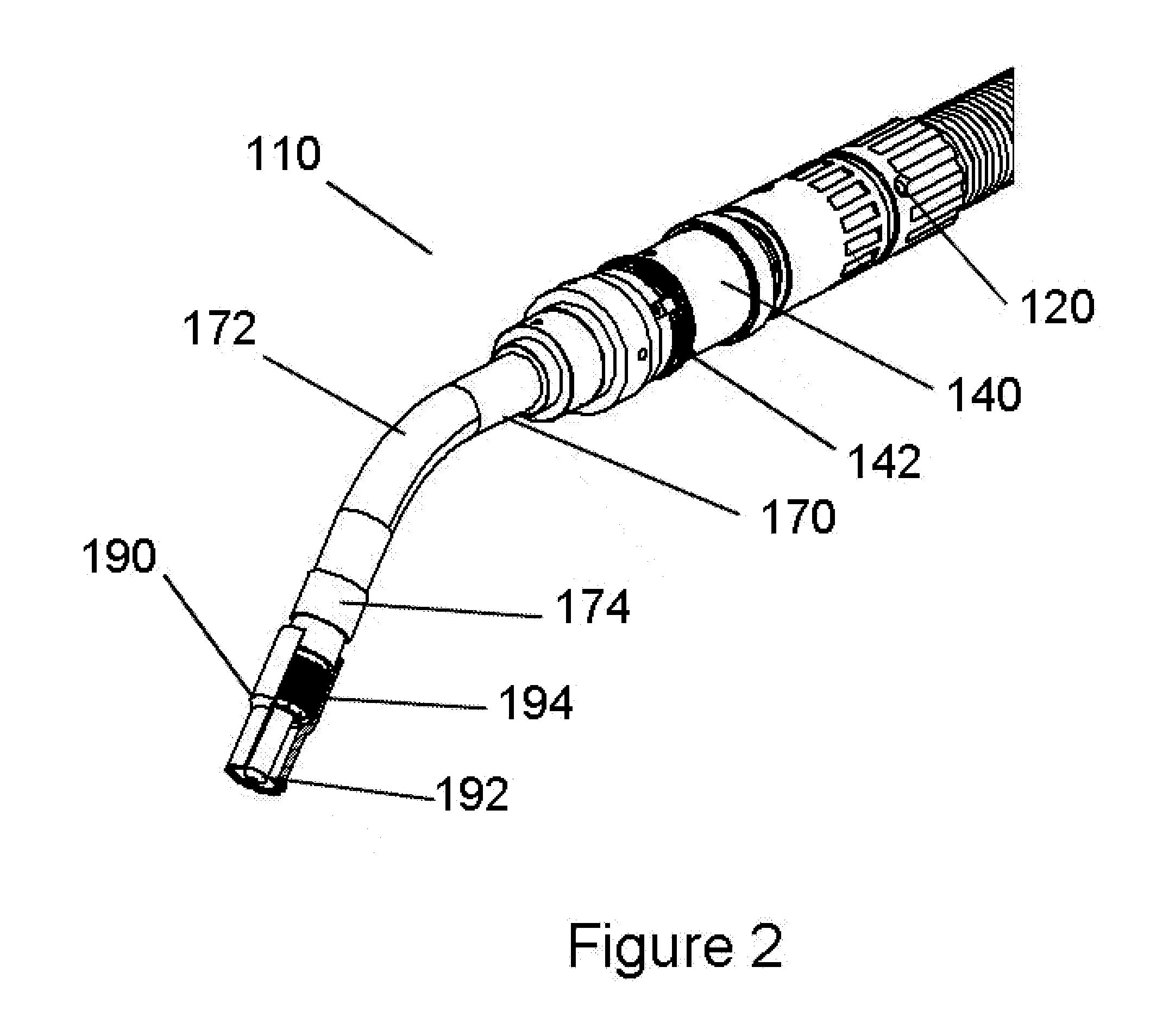
[0040]The rotary welding assembly 110 comprises a rotary coolant assembly 140, a conductive tube assembly 170, and a consumable suite 190 as depicted in FIG...

second embodiment

[0051]In a second embodiment in accordance with the present disclosure, there is provides a TIG robotic welding torch 200. The TIG welding torch generally comprises a rotary welding assembly 210, a supply conduit 220, a source of filler wire 230, a source of inert gas and a power source. A depiction of a TIG welding torch in accordance with the present disclosure is depicted in FIG. 7. When utilizing a coolant, the welding torch will also require a coolant source for providing cooled water or air to the rotary welding assembly.

[0052]The TIG welding torch may be fastened to the robotic unit via a housing flange which mounts directly to the front robotic flange. The rotary movement of the rotary welding assembly may be realized from the housing flange 202, through a rotary joint assembly 204 as shown in FIG. 8. A depiction of the rotary joint assembly 204 is depicted in FIG. 9. The rotary joint assembly 204 engages the rotary shaft via a slot 206 and is secured in place with fasteners...


PUM


Abstract

A rotary robotic welding torch that enables the welding process in a robotic unit. The rotary welding torch allows for clockwise and counterclockwise rotation during the welding process, while being supplied with an uninterrupted supply of inert gas and electrical current. The rotary robotic welding torch may also be supplied with an uninterrupted supply of coolant and/or electrode/filler wire during the welding process.

Description

FIELD[0001]The present disclosure generally relates to welding torches for robotic units. More particularly, the present disclosure relates to a welding torch for a robotic unit which allows rotation of the torch in the clockwise or counterclockwise direction.BACKGROUND[0002]Welding torches are often used in conjunction with a robotic unit. This is particularly advantageous in a manufacturing setting where multiple welds are needed in a precise fashion. Two types of welding torches often used with robotic units are metal inert gas (“MIG”) welding torches and tungsten inert gas (“TIG”) welding torches. When used with a robotic unit, the welding torch may be fastened to the robotic unit, at a robotic interface and supplied with electrical current, electrode wire, a supply of inert gas, and a supply of coolant. Such materials are typically provided to the welding torch via one or more cable assemblies.[0003]Metal inert gas (“MIG”) welding torches may be used in a variety of application...

Claims


Application Information

Patent Timeline
IPC IPC(8): B23K9/00
CPCB23K9/287B23K9/285
Inventor CENKO, ARBEN
Owner CENKO ARBEN
Why Eureka
Try Eureka