Light emitting device, light receiving system and image pickup system

Inactive Publication Date: 2011-08-18
HONDA MOTOR CO LTD
View PDF5 Cites 6 Cited by
  • Summary
  • Abstract
  • Description
  • Claims
  • Application Information

AI Technical Summary

Benefits of technology

[0013]The present invention has been made in view of the aforementioned problems. It is an object of the present invention to provide a light-emitting device, which is capable of reducing heat generation and power consumption as well as increasing the S / N ratio of signal light, and which can be used in various applications that make use of light emission.
[0014]Another object of the present invention is to provide a light-detecting system and an image sensing system, which incorporate therein the above light-emitting device, for reducing the effect of a noise component of ambient light, and for increasing synchronism between acquisition of a luminance value when an object is irradiated and acquisition of a luminance value when the object is not irradiated.

Problems solved by technology

Reflected light from the object includes not only a signal light component based on the reflected laser beam, but also noise due to sunlight, and shot noise (a noise component of ambient light) of sunlight.
Inasmuch as the object is irradiated with continuous light over the given period (e.g., during one frame period), a time interval corresponding to the above given period needs to be provided between acquisition of a luminance value when the object is irradiated and acquisition of a luminance value when the object is not irradiated, thus making it impossible to achieve synchronism between acquisition of the luminance value when the object is irradiated and acquisition of the luminance value when the object is not irradiated.
Therefore, even if a semiconductor laser is used simply as a light-emitting device, it is difficult for the semiconductor laser to be used in various applications that make use of light emission.Document 1:Ryohei Miyagawa and Takeo Kanade, “CCD-Based Range-Finding Sensor”, IEEE Transactions on Electron Devices, Vol. 44, No. 10, October 1997, pp.

Method used


Image

  • Light emitting device, light receiving system and image pickup system
  • Light emitting device, light receiving system and image pickup system
  • Light emitting device, light receiving system and image pickup system

Examples


Embodiment Construction

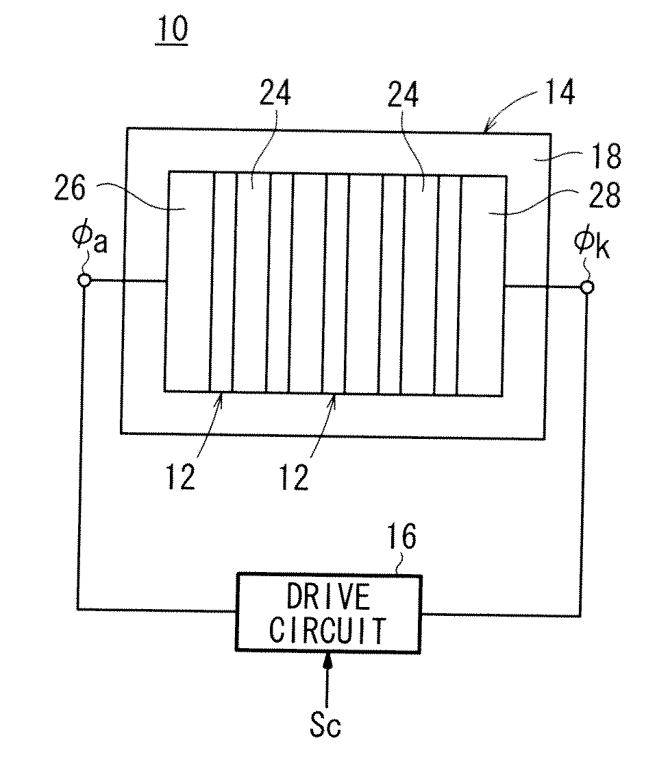
[0048]A light-emitting device, a light-detecting system, and an image sensing system according to an embodiment of the present invention will be described below with reference to FIGS. 1 through 14.

[Light-Emitting Device]

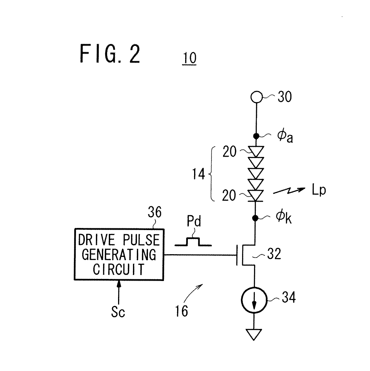
[0049]As shown in FIG. 1, a light-emitting device 10 according to an embodiment of the present invention comprises a diffused light source 14 including an array of semiconductor laser bars 12, and a drive circuit 16 for supplying a single drive pulse Pd (see FIG. 2) to the diffused light source 14 based on a light emission command Sc input thereto, so as to enable the diffused light source 14 to emit a single pulse of light. In FIG. 1, the diffused light source 14 includes an array of five semiconductor laser bars 12 having respective laser beam emission surfaces, all of which are exposed on one surface (light emission surface) of the diffused light source 14.

[0050]The semiconductor laser bars 12 of the diffused light source 14 are arranged with longitudinal axes th...


PUM


Abstract

A light emitting device has: a dispersion light source wherein a plurality of semiconductor laser bars are arranged; and a drive circuit which makes the dispersion light source output at least one pulsed beam by supplying at least one drive pulse to the dispersion light source. In the dispersion light source, a plurality of semiconductor laser bars are arranged on a base, and furthermore, heat dissipating plates are arranged between the semiconductor laser bars. The pulse width of the pulsed beam outputted from the dispersion light source is longer than 1 femtosecond but shorter than 0.25 second, and the energy of the single pulsed beam is less than 66.8 μ[J].

Description

TECHNICAL FIELD[0001]The present invention relates to a light-emitting device, which can be used in various applications that make use of light emission. The present invention also relates to a light-detecting system (light receiving system) and an image sensing system (image pickup system), which incorporate such a light-emitting device therein.BACKGROUND ART[0002]Applications that make use of light emission include an optical space transmission system and a rangefinding system.[0003]One known rangefinding system, which measures a distance up to an object in a contactless manner, for example, employs a time-of-flight (TOF) process. According to the TOF process, light is emitted toward the object, and a period of time, which is consumed after the light has been emitted toward the object and until the light bounces off the object and returns, is measured, so that the distance up to the object can be measured based on the period of time and the velocity of light (see Japanese Laid-Ope...

Claims


Application Information

Patent Timeline
IPC IPC(8): H01J13/32
CPCG01S7/4814G01S7/4816G01S7/4876H01L27/14601G01S7/484
Inventor KAMIYAMA, TOMOYUKI
Owner HONDA MOTOR CO LTD
Why Eureka
Try Eureka