
Method for observing fluid and fluid flow observation

a technology for observing fluids and fluids, applied in the direction of fluid speed measurement, speed/acceleration/shock measurement, instruments, etc., can solve the problems of difficult to observe the interior of slurry, inability to successfully observe the movement of particles in fluids containing inorganic particles, etc., to improve the visibility of particles, increase the translucency of fluid, and improve the viscosity of fluid

Inactive Publication Date: 2011-08-18
NGK INSULATORS LTD
View PDF12 Cites 10 Cited by
  • Summary
  • Abstract
  • Description
  • Claims
  • Application Information

AI Technical Summary

Benefits of technology

[0006]In view of the problems described above, the present invention can ensure the observation of the movement of a fluid containing inorganic particles. Accordingly, it is a principal object of the present invention to provide a method for observing a fluid and a fluid for flow observation.
[0007]As a result of diligent research to achieve the principal object, the present inventors completed the present invention by finding that the movement of a fluid containing inorganic particles can be observed with higher reliability by adding inorganic particles each having a planar surface to the fluid and irradiating the fluid with light.
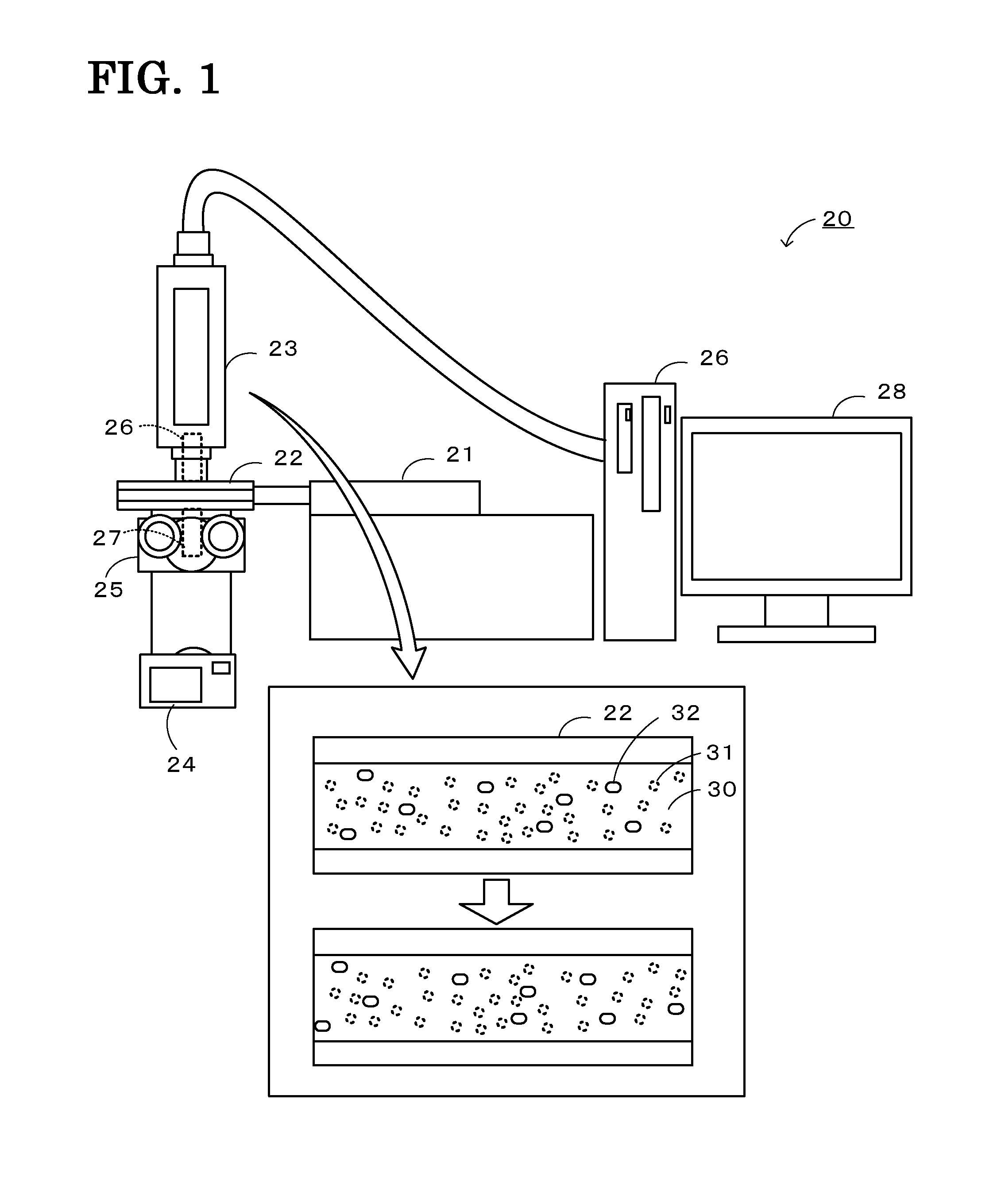
[0010]A method for observing a fluid and a fluid for flow observation according to the present invention can ensure the observation of the movement of a fluid containing inorganic particles. This is because the fluid for flow observation contains a dispersion medium to be observed and a viscosity modifier for adjusting the fluid viscosity. The concentration of inorganic particles can be controlled via the dispersion medium, and the viscosity of the fluid can be controlled via the viscosity modifier. These can increase the translucency of the fluid. Furthermore, the fluid for flow observation contains inorganic particles to be observed each having a planar surface. Upon light irradiation, it is assumed that the planar surfaces block or reflect light, thereby improving the visibility of the particles. This can ensure the observation of the movement of the fluid containing the inorganic particles. In addition to the inorganic particles to be observed each having a planar surface, the fluid for flow observation may further contain inorganic particles to be observed not having a planar surface.

Problems solved by technology

It is therefore difficult to observe the interior of slurry.
A method for observing a fluid described in Japanese Unexamined Patent Application Publication No. 2003-84005 does not take such a fluid into account and cannot successfully observe the movement of particles in fluids containing inorganic particles.

Method used


Image

  • Method for observing fluid and fluid flow observation
  • Method for observing fluid and fluid flow observation
  • Method for observing fluid and fluid flow observation

Examples


experimental example 1

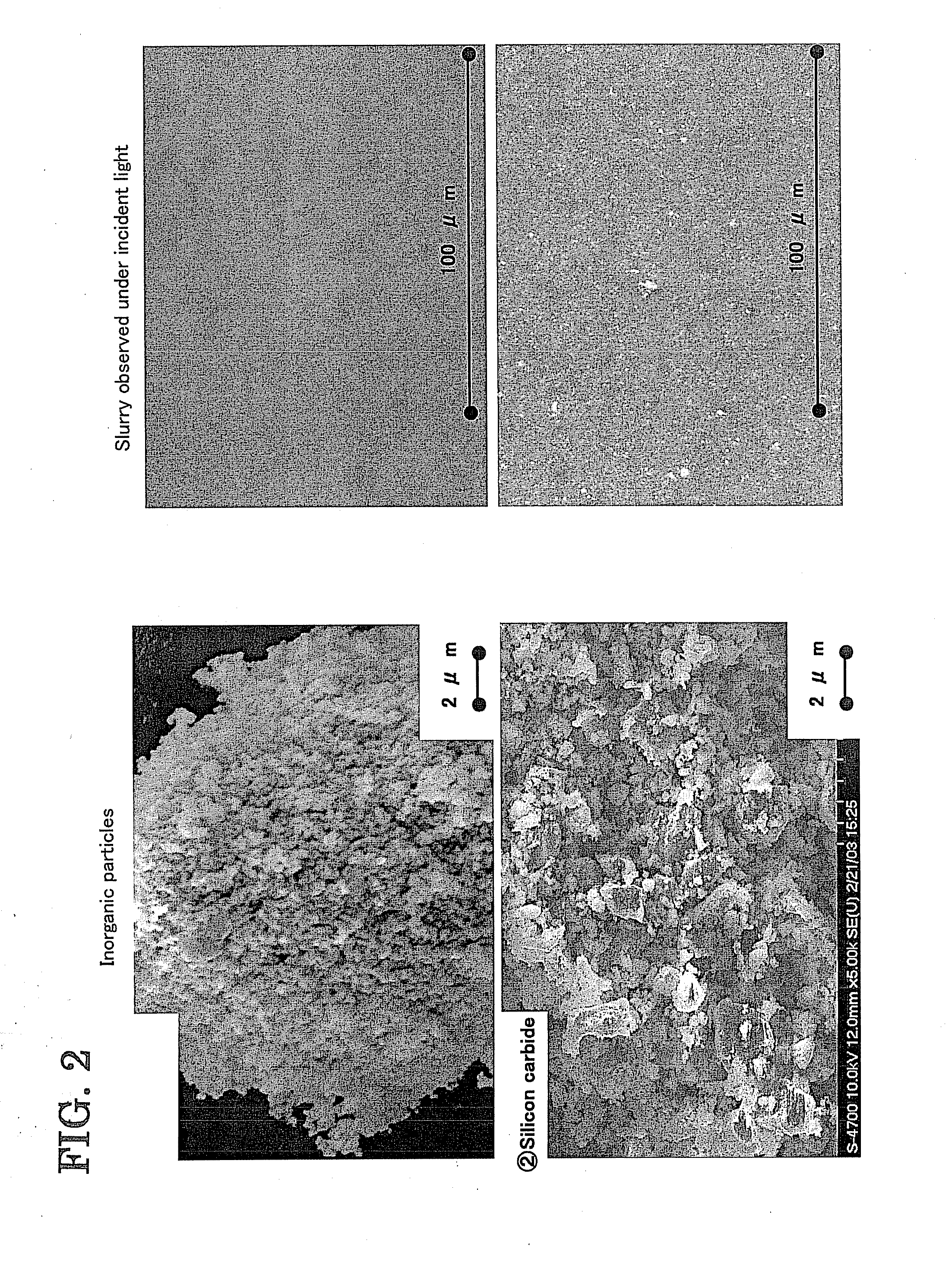
[0034]A slurry containing inorganic particles was prepared as a fluid for flow observation so as to closely resemble a fluid for flow analysis. 100 parts by weight of silicon carbide particles (manufactured by Superior Graphite) serving as inorganic particles to be observed, 50 parts by weight of a mixture of triacetin and an organic dibasic acid ester (at a weight ratio of 1:9) serving as a dispersion medium to be observed, and 4.2 parts by weight of a dispersing aid (a polymerized alkylammonium salt compound having an acid group) serving as a viscosity modifier were mixed. The volume parts of the raw materials were 31 volume parts of the inorganic particles, 45 volume parts of the dispersion medium, and 4 volume parts of the dispersing aid.

experimental example 2

[0035]A slurry containing inorganic particles was prepared as a fluid for flow observation so as to closely resemble a fluid for flow analysis. 100 parts by weight of silicon carbide particles (manufactured by Superior Graphite) serving as inorganic particles to be observed, 77.8 parts by weight of a mixture of triacetin and an organic dibasic acid ester (at a weight ratio of 1:9) serving as a dispersion medium to be observed, 6 parts by weight of a dispersing aid (a polymerized alkylammonium salt compound having an acid group) serving as a viscosity modifier, and 1.1 parts by weight of polyvinyl acetal resin (a molecular weight of approximately 23,000, a butyral content of 74% by mole) serving as a viscosity modifier (binder) were mixed. The volume parts of the raw materials were 31 volume parts of the inorganic particle, 71 volume parts of the dispersion medium, 6 volume parts of the dispersing aid, and 1 volume parts of the binder.

experimental example 3

[0036]A slurry containing inorganic particles was prepared as a fluid for flow observation. 100 parts by weight of silicon carbide particles (manufactured by Superior Graphite) serving as inorganic particles to be observed, 75 parts by weight of a mixture of triacetin and an organic dibasic acid ester (at a weight ratio of 1:9) serving as a dispersion medium to be observed, and 10 parts by weight of a polycarboxylic acid copolymer serving as a viscosity modifier (dispersing aid) were mixed. The volume parts of the raw materials were 31 volume parts of the inorganic particles, 68 volume parts of the dispersion medium, and 10 volume parts of the dispersing aid.

[0037]Measurement of Particle Size Distribution

[0038]The particle size distribution of the zirconia particles and the silicon carbide particles used as inorganic particles was measured. The particle size of inorganic particles was determined as a median size (D50) using water as a dispersion medium with a laser diffraction / scatt...


PUM


Abstract

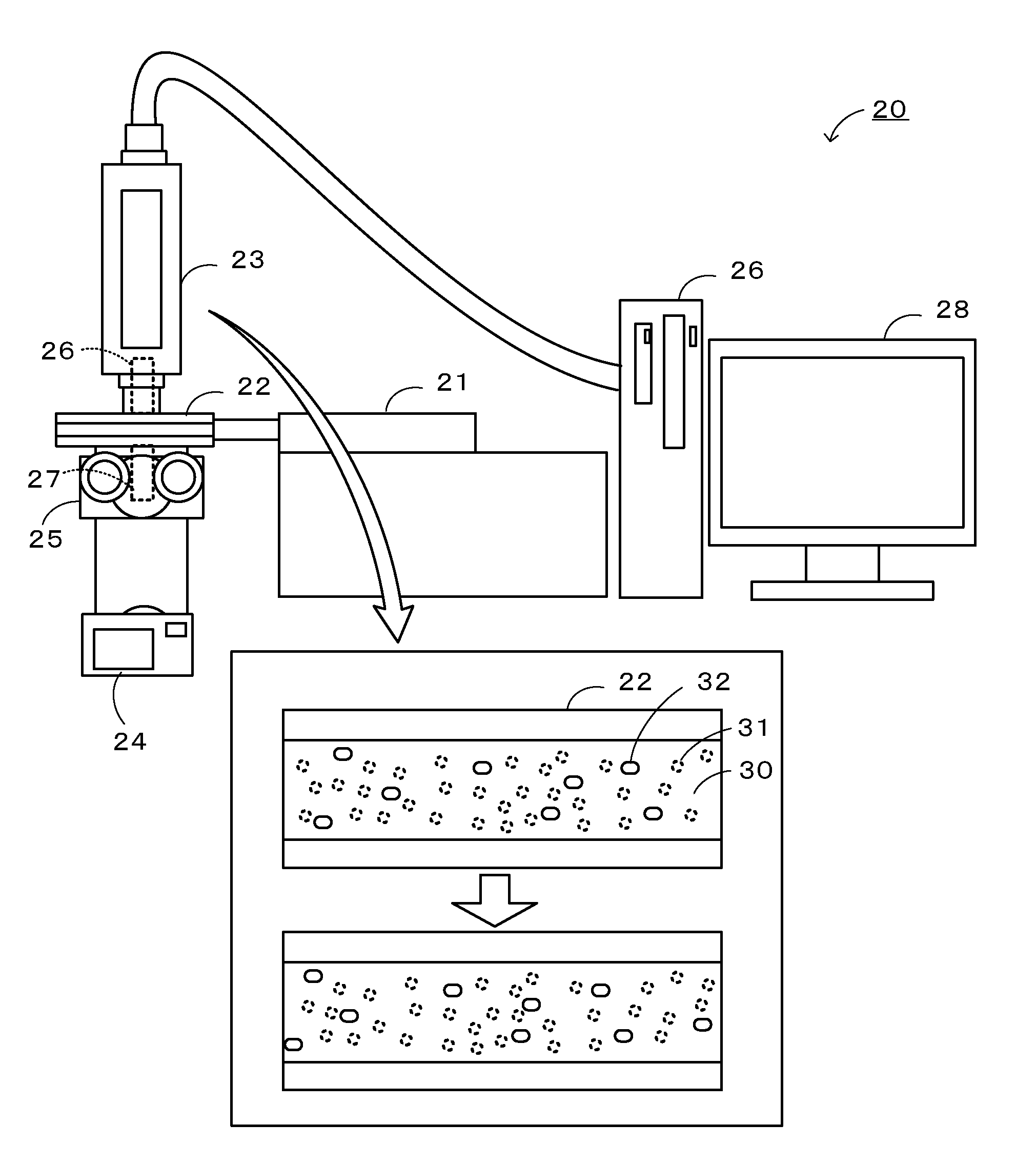
A fluid observation apparatus 20 can perform a method for observing a fluid by PIV. The method for observing a fluid includes capturing an image of inorganic particles in a fluid for flow observation 30 by irradiating the fluid for flow observation 30 passing through a flow channel with light, the fluid for flow observation 30 containing inorganic particles to be observed each having a planar surface, a dispersion medium to be observed, and a viscosity modifier. The fluid for flow observation 30 is high-viscosity non-Newtonian slurry containing inorganic particles. The fluid for flow observation 30 may be a simulated fluid for a fluid for flow analysis. The simulated fluid closely resembles the particle size of inorganic particles to be analyzed and the viscosity of the fluid for flow analysis. The fluid for flow analysis contains the inorganic particles to be analyzed and a dispersion medium to be analyzed.

Description

BACKGROUND OF THE INVENTION[0001]1. Field of the Invention[0002]The present invention relates to a method for observing a fluid and a fluid for flow observation.[0003]2. Description of the Related Art[0004]Heretofore, particle image velocimetry (hereinafter referred to as PIV) has been used as a method for observing a fluid. Particle image velocimetry involves adding particles following the flow (tracer particles) to the fluid, irradiating the fluid with a pulsed laser beam to track the movement of the fluid, following the motion of the tracer particles with a video camera or the like, capturing images of the travel distance of the particles at sufficiently small time intervals on a flow time scale, and determining the distance and direction of the travel (see, for example, Japanese Unexamined Patent Application Publication No. 2003-84005).SUMMARY OF THE INVENTION[0005]Fluids can be classified into Newtonian fluids, the viscosity of which is independent of shear rate and time, and n...

Claims


Application Information

Patent Timeline
Patent Type & Authority Applications(United States)
IPC IPC(8): G01P3/36
CPCG01N15/0227G01P5/20G01P5/001G01N2015/0294
Inventor YOSHIOKA, KUNIHIKOISHIBASHI, SATOSHI
Owner NGK INSULATORS LTD
Learn More