Method and apparatus for antenna radiation pattern sweeping

Inactive Publication Date: 2011-08-18
QUINTEL CAYMAN LTD
View PDF11 Cites 35 Cited by
  • Summary
  • Abstract
  • Description
  • Claims
  • Application Information

AI Technical Summary

Problems solved by technology

However, Opportunistic Beamforming, Antenna Hopping, Phase Sweeping and even MIMO techniques are employed at a single cell or sector level, and not operated in a co-ordinated network level manner.

Method used


Image

  • Method and apparatus for antenna radiation pattern sweeping
  • Method and apparatus for antenna radiation pattern sweeping
  • Method and apparatus for antenna radiation pattern sweeping

Examples


Embodiment Construction

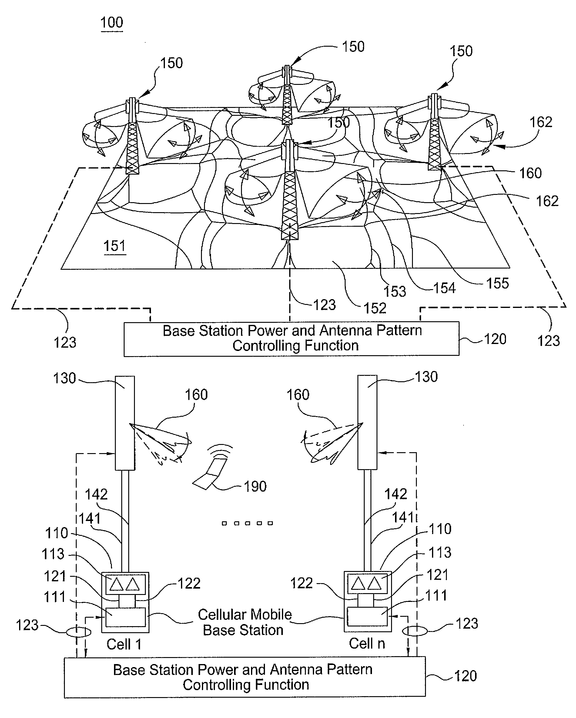
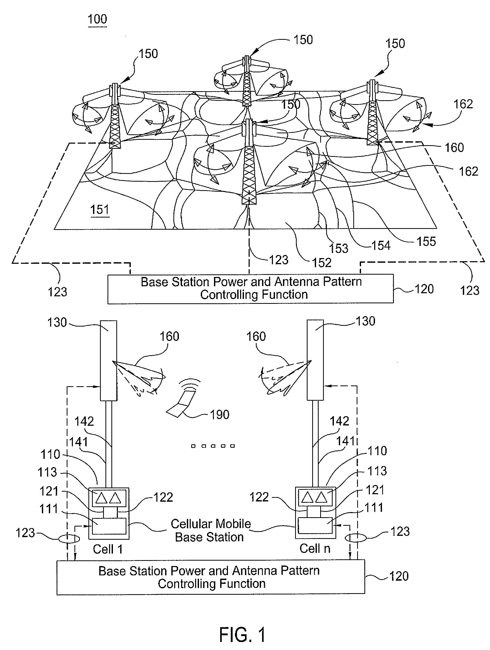
[0014]It should be noted that co-ordinated tilt switching techniques can be used with communications systems using MIMO techniques. For example, these methods may rely on co-ordinated discrete “switching” of adjacent sector beam tilts on a co-ordinated frame by frame basis. The result is that no user is ever at cell edges when being served with data. As such, the technique does not rely upon feedback from the user terminals as to the user downlink signal quality and allows for a scheduling algorithm (located at the base station) to make the decision of when to schedule data to the user(s). The technique forces a two-state signal quality rather than a continuously varying state of signal quality; as such, the method assumes knowledge when it has opportunity to send data and to which users as a function of time. However, this technique is not optimized for all users since a bi-state tilt switching process means that (fixed location) users will experience only two states of signal qual...


PUM


Abstract

A system and method for antenna radiation pattern sweeping in wireless networks, e.g., cellular networks, are disclosed. For example, the system comprises a first base station associated with a first antenna assembly for providing a first antenna radiation pattern over a first footprint of a first cell, a second base station associated with a second antenna assembly for providing a second antenna radiation pattern over a second footprint of a second cell, wherein there is an overlap between the first footprint and the second footprint, and a controller for controlling the first base station and the second base station to continuously provide a variation of the first antenna radiation pattern and the second antenna radiation pattern in a co-ordinated manner for maintaining the overlap between the first footprint and the second footprint.

Description

[0001]This application claims the benefit of U.S. Provisional Application No. 61 / 296,394 filed on Jan. 19, 2010, which is herein incorporated by reference.FIELD OF THE DISCLOSURE[0002]The present disclosure generally relates to the field of wireless communications, and more specifically relates to antenna radiation pattern sweeping in wireless networks, e.g., cellular networks.BACKGROUND[0003]Many communications systems (such as Long Term Evolution (LTE) 3G radio, High Speed Packet Access (HSPA), Worldwide Interoperability for Microwave Access (WiMAX) systems and the like) are designed to use multiple input, multiple output (MIMO) antenna techniques which compute optimal power and phase weightings into two or more transmission antennas and one or more receiving antennas to maximize the carrier-to-interference ratio (C / I) on a per-user basis and hence maximize data throughput rates. MIMO implementations rely upon using two or more de-correlated or partially orthogonal different multi...

Claims


Application Information

Patent Timeline
Patent Type & Authority Applications(United States)
IPC IPC(8): H04W72/04H01Q3/01
CPCH01Q1/246H04W16/28H01Q3/26
Inventor BARKER, DAVID EDWINRADOUSKY, KEITH HAL
Owner QUINTEL CAYMAN LTD
Why Eureka
Try Eureka