Rotary engine lip-seal apparatus and method of operation therefor

Active Publication Date: 2011-08-18
PEKRUL MERTON W
View PDF100 Cites 34 Cited by
  • Summary
  • Abstract
  • Description
  • Claims
  • Application Information

AI Technical Summary

Problems solved by technology

All internal combustion engines suffer from poor efficiency; only a small percentage of the potential energy is released during combustion as the combustion is invariably incomplete.
Even with the support system, a significant quantity of pollutants are released into the atmosphere as a result of incomplete combustion when using an internal combustion engine.
Because internal combustion engines depend upon the rapid and explosive combustion of fuel within the engine itself, the engine must be engineered to withstand a considerable amount of heat and pressure.
These are drawbacks that require a more robust and more complex engine compared to external combustion engines of similar power output.
The high rotational speeds present several engineering challenges that typi

Method used


Image

  • Rotary engine lip-seal apparatus and method of operation therefor
  • Rotary engine lip-seal apparatus and method of operation therefor
  • Rotary engine lip-seal apparatus and method of operation therefor

Examples


Embodiment Construction

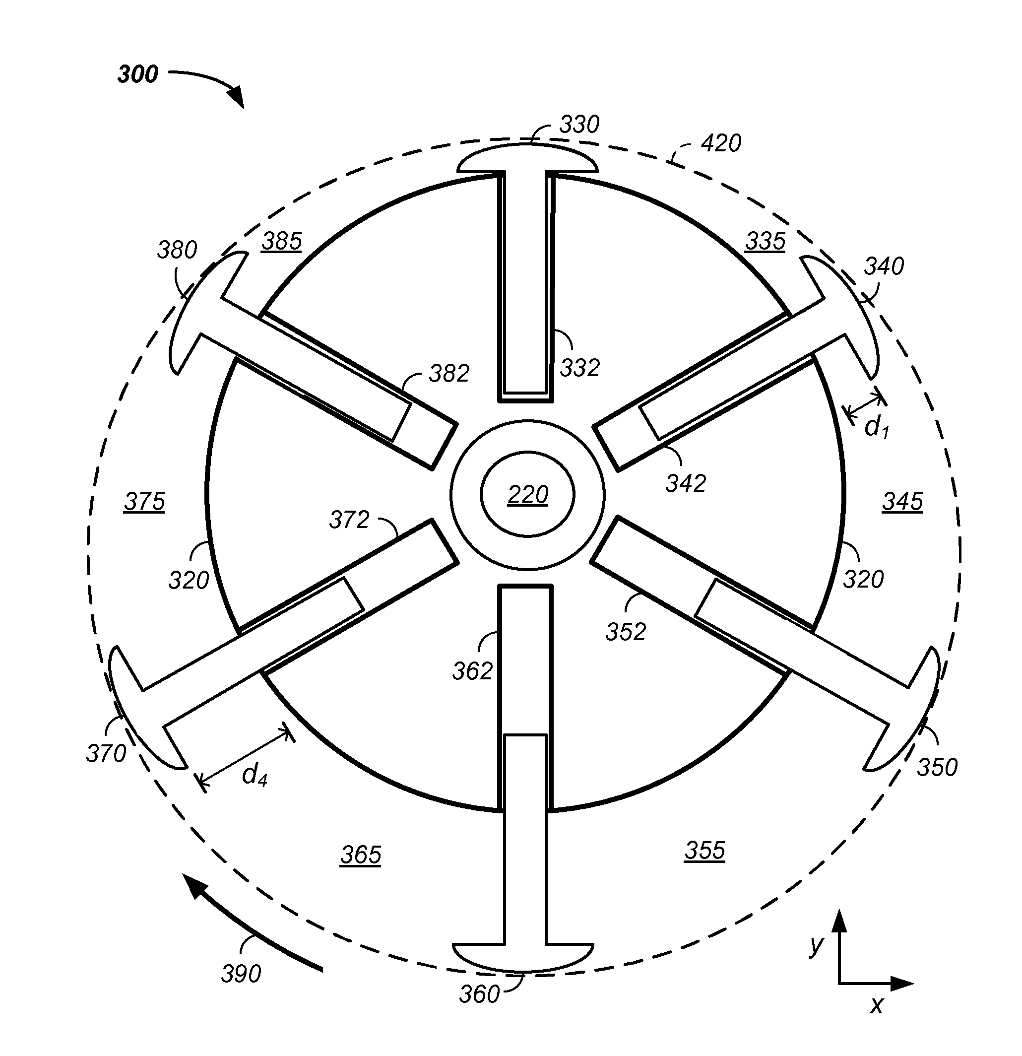
[0151]The invention comprises a rotary engine method and apparatus configured with at least one lip seal. A lip seal restricts fuel flow from a fuel compartment to a non-fuel compartment and / or fuel flow between fuel compartments, such as between a reference expansion chamber and any of an engine: rotor, vane, housing, and / or a leading or trailing expansion chamber. Types of lip seals include: vane lip seals, rotor lip seals, and rotor-vane slot lip seal. Generally, lip seals dynamically move or deform as a result of fuel movement or pressure to seal a junction between a sealing surface of the lip seal and a rotary engine component. For example, a vane lip seal sealing to the inner housing dynamically moves along the y-axis until an outer surface of the lip seal seals to the housing.

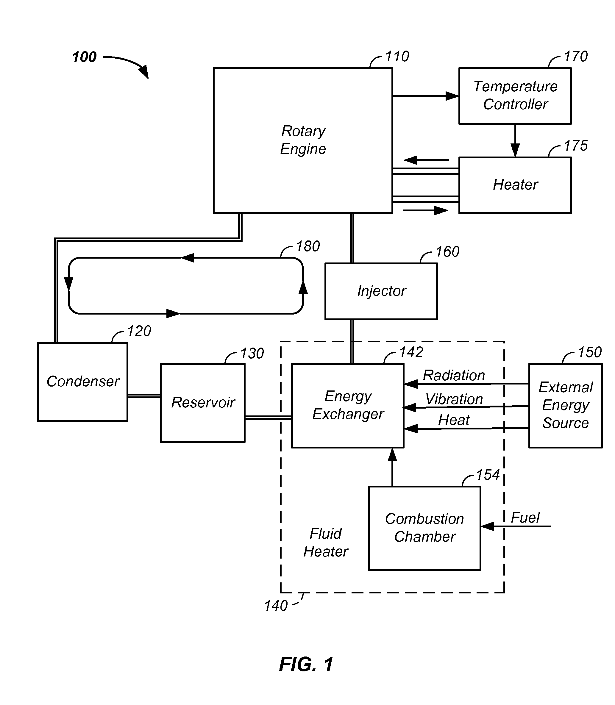
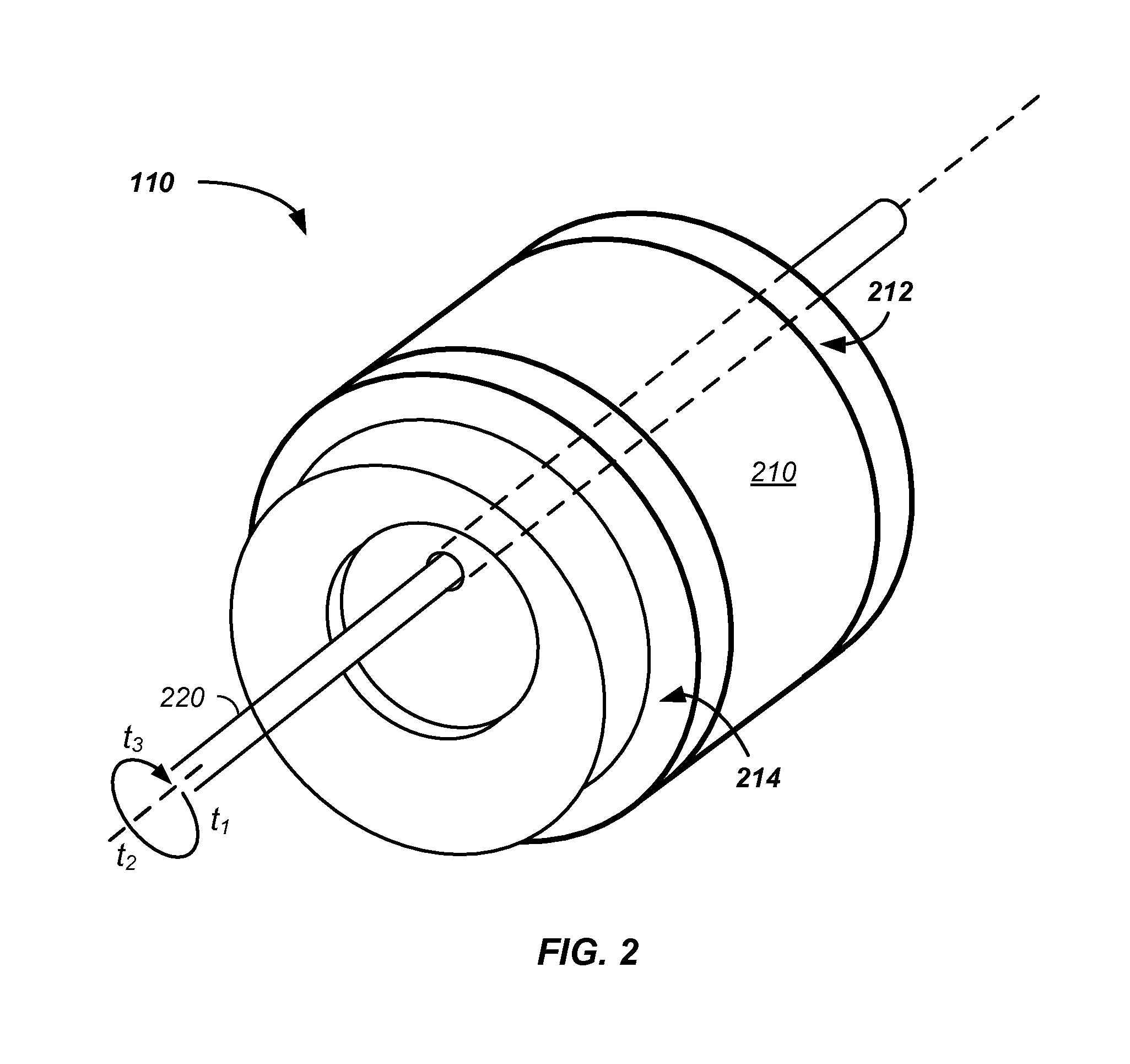
[0152]In another embodiment, the rotary engine method and apparatus uses an offset rotor. The rotary engine is preferably a component of an engine system using a recirculating liquid / vapor.

[0153]In yet a...


PUM


Abstract

The invention comprises a rotary engine method and apparatus configured with a lip seal. A lip seal restricts fuel flow from a fuel compartment to a non-fuel compartment and/or fuel flow between fuel chambers, such as between a reference expansion chamber and any of an engine: rotor, vane, housing, and/or a leading or trailing expansion chamber. In separate states, high pressure and low pressure force sealing movement of the lip seal, respectively. The lip seal is optionally used in combination with a cap seal to form a dynamic seal. The dynamic seals ability to track a noncircular path are particularly beneficial for use in a rotary engine having an offset rotor and with a non-circular inner rotary engine compartment having engine wall cut-outs and/or build-ups. The dynamic sealing forces further provide cap sealing forces over a range of temperatures, pressures, fuel flow rates, varying loads, and operating engine rotation rates.

Description

CROSS-REFERENCES TO RELATED APPLICATIONS[0001]This application is a continuation-in-part of U.S. patent application no. 13 / 069,165 filed Mar. 22, 2011, which.[0002]is a continuation-in-part of U.S. patent application no. 13 / 042,744 filed Mar. 8, 2011;[0003]is a continuation-in-part of U.S. patent application no. 13 / 031,228 filed Feb. 20, 2011;[0004]is a continuation-in-part of U.S. patent application no. 13 / 031,190 filed Feb. 19, 2011;[0005]is a continuation-in-part of U.S. patent application no. 13 / 041,368 filed Mar. 5, 2011, which is a continuation-in-part of U.S. patent application no. 13 / 031,755 filed Feb. 22, 2011, which is a continuation-in-part of U.S. patent application no. 13 / 014,167 filed Jan. 26, 2011, which[0006]is a continuation-in-part of U.S. patent application Ser. No. 12 / 705,731 filed Feb. 15, 2010, which is a continuation of U.S. patent application Ser. No. 11 / 388,361 filed Mar. 24, 2006, now U.S. Pat. No. 7,694,520, which is a continuation-in-part of U.S. patent a...

Claims


Application Information

Patent Timeline
IPC IPC(8): F01C19/02
CPCF01C1/3445F01C1/44F01C19/12F01C21/0863F23C2900/99005F04C2240/20F22B29/062F22B31/0038F23C99/001F01C21/0881
Inventor PEKRUL, MERTON W.
Owner PEKRUL MERTON W
Why Eureka
Try Eureka