Hot Blast Stove Dome and Hot Blast Stove

a technology of hot blast stove and dome, which is applied in the field of hot blast stove dome, can solve the problems of affecting the heating effect of the stove, so as to achieve significant engineering, material and construction savings, and reduce or eliminate cracking

Active Publication Date: 2011-08-18
ALLIED MINERAL PROD LLC
View PDF47 Cites 9 Cited by
  • Summary
  • Abstract
  • Description
  • Claims
  • Application Information

AI Technical Summary

Benefits of technology

[0011]The vertical expansion joint which is provided in the dome allows the dome portion supported by the combustion chamber wall to grow independently of the dome portion supported by the checker chamber wall. Thus, the thermal effect of the wall expansion on the combustion chamber side has no adverse impact on the dome's structural integrity and cracking is reduced or eliminated. Additionally, the hot blast stove dome of the present invention allows the elimination of the insulation and dense walls in the combustion chamber, thereby providing significant engineering, material and construction savings.

Problems solved by technology

This difference in expansion over the large height of the blast stoves, typically 200, 300 or more feet tall, contributes to the formation of cracks in the dome and often leads to premature dome failure.
Once the hot face of the refractory dome starts to crack, insulation between the dome and the metal shell is compromised.
This results in local hot spots on the steel shell.
In some cases, the heavy cracking is so excessive and damage on the inside of the dome is so large that locally the dome collapses and repairs on the inside are required.
All of these described repairs significantly contribute to financial loss due to maintenance costs and the inability to operate the blast stove during the repair maintenance.
Not only does this design require additional engineering, material and construction, its effect in preventing dome cracks and deterioration of the dome structure over the life of the blast stove has been limited as variations in the thermal expansion of the supporting wall in the area of the combustion chamber still occur and often cause significant dome cracking.

Method used


Image

  • Hot Blast Stove Dome and Hot Blast Stove
  • Hot Blast Stove Dome and Hot Blast Stove
  • Hot Blast Stove Dome and Hot Blast Stove

Examples


Embodiment Construction

[0019]The present invention is directed to a hot blast stove dome and to a hot blast stove including a dome according to the invention.

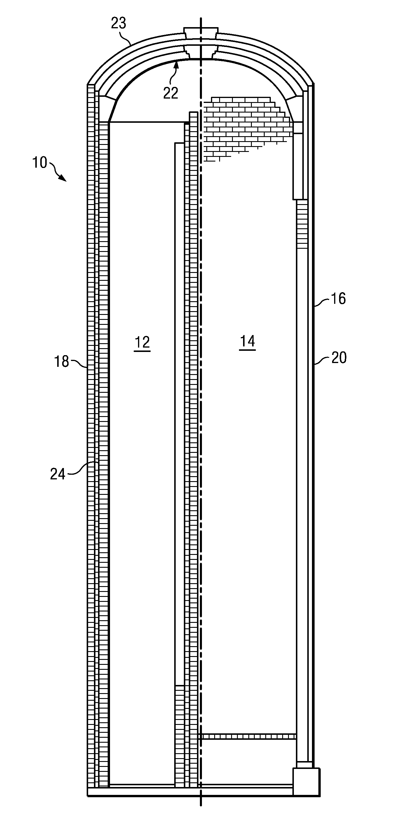
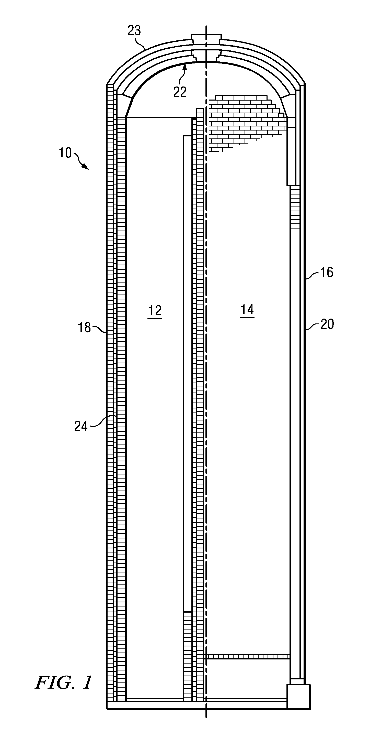
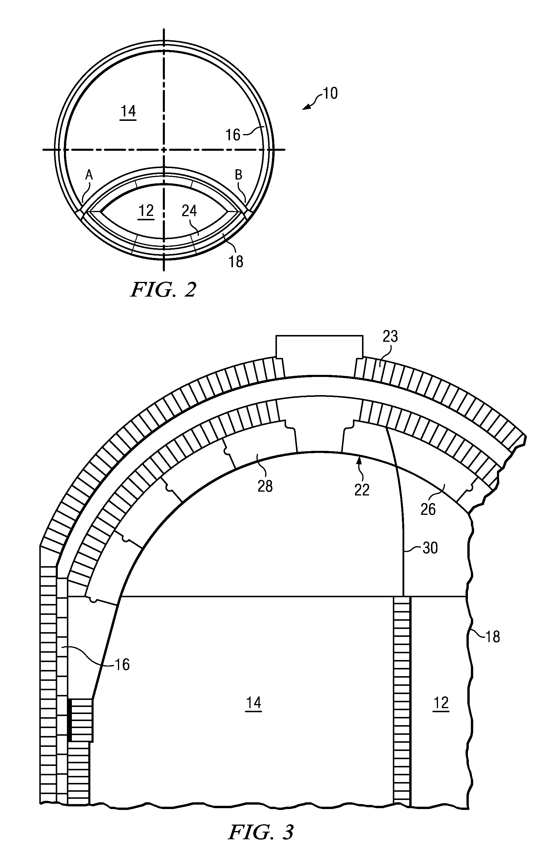
[0020]A typical hot blast stove is shown schematically in FIGS. 1 and 2, generally indicated at 10. The hot blast stove 10 comprises a combustion chamber 12, a checker chamber 14, a cylindrical housing 16 comprising a combustion chamber wall 18 and a checker chamber wall 20, and a refractory dome 22. The housing 16 conventionally comprises a metal shell and a refractory lining, and a metal dome shell 23 encompasses the refractory dome 22. As shown in FIGS. 1 and 2, the portion of the housing comprising the combustion chamber wall 18 includes additional wall layers 24, typically formed of an insulating layer and a dense refractory, to reduce increased vertical expansion of the wall in the vicinity of the combustion chamber 12. As additionally shown, the combustion chamber wall 18 separates the combustion chamber 12 from the checker chamber 14. The dom...


PUM


Abstract

A hot blast stove dome comprises a first dome portion adapted for support on a combustion chamber wall of a hot blast stove, and a second dome portion adapted for support on a checker chamber wall of a hot blast stove, wherein a vertical expansion joint is provided between the first dome portion and the second dome portion and is adapted to allow the first dome portion and the second dome portion to independently accommodate vertical expansion of their respective supporting walls. The dome is suitably provided in a hot blast stove which comprises a combustion chamber, a checker chamber, a cylindrical housing comprising a combustion chamber wall and a checker chamber wall.

Description

RELATED APPLICATIONS[0001]The present application claims priority under 35 U.S.C. §119 to U.S. Application Ser. No. 61 / 303,894 filed Feb. 12, 2010, incorporated herein by reference.FIELD OF THE INVENTION[0002]The present invention is directed to a hot blast stove dome and to a hot blast stove having an internal combustion chamber and including the dome of the invention. The hot blast stove dome provides improved resistance to thermal dome damage in a hot blast stove having an internal combustion chamber and results in significant reductions in engineering, materials and construction costs as compared with common conventional apparatus.BACKGROUND OF THE INVENTION[0003]Hot blast stoves, sometimes referred to as blast furnace stoves, are typically employed in iron manufacturing to preheat combustion air before it enters into a blast furnace. A hot blast stove typically has a cylindrical, silo-shaped wall structure constructed of refractory and insulating brick, and surrounded by a meta...

Claims


Application Information

Patent Timeline
Patent Type & Authority Applications(United States)
IPC IPC(8): F27D1/14
CPCC21B9/02C21B9/10F27D1/0023F27D17/004F27D1/025F27D1/10F27D1/003
Inventor VAN LAAR, FLORISVAN LAAR, JACOBUS
Owner ALLIED MINERAL PROD LLC
Why Eureka
Try Eureka