Manufacturing method of valve sealant fitting

a valve sealant and manufacturing method technology, applied in the direction of valve housings, functional valve types, machines/engines, etc., can solve the problems of degrading the reliability of the sustaining part as a component of a high pressure valve or an ultra-low temperature valve, and affecting the quality of the sealing fitting. , to achieve the effect of significant material and production unit price savings and safe and uniform maintenance of the quality of the sealing fitting

Inactive Publication Date: 2013-01-29
KIM DO A +1
View PDF4 Cites 0 Cited by
  • Summary
  • Abstract
  • Description
  • Claims
  • Application Information

AI Technical Summary

Benefits of technology

[0015]According to a valve sealant fitting and a method of manufacturing the same of the present invention, the valve sealant has a complete sealing property, so that it can completely prevent the fluid and gas from being leaked even when the sealant fitting is applied for a high pressure valve or an ultra-low temperature valve, many processes can be decreased, significant material and production unit price savings can be expected, and the quality of the sealant fitting can also be safely and uniformly maintained particularly at the time of manufacturing the sealant fitting.

Problems solved by technology

However, according to the conventional sealant fitting as described above, the press-bent sustaining part for mounting the spring in the fitting, preventing the spring from being deviated and sustaining the bottom surface is disposed on the body at the bottom surface of the spring, so that the sustaining part is structurally weak.
However, the reliability of the sustaining part as a component of a high pressure valve or an ultra-low temperature valve is degraded when it is applied for the high pressure valve due to a high possibility of having cracks or damages in use.
That is, even when an external screw thread of the lower screw coupling part disposed for easy coupling of the sealant fitting at a predetermined position of the valve is coupled with an internal screw thread of the valve by a strong coupling force, fine gaps and corrosion may occur when a high valve pressure is applied thereto or when the valve is used for a long time, resulting in a leakage of sealant, lubricant, fluid or gas.
In the meantime, many times, processes and costs are required for processing and manufacturing the vent cap and the ball seat among the components of the conventional sealant fitting, thereby decreasing the productivity, economical efficiency, quality and safety thereof.
A process for internal groove, a process for lower spring sustaining part, a process for forming a groove for closely adhering the ball and the fluid communication, a chamfering process and so on are also required for processing the internal groove formed in the ball seat, the lower spring sustaining part, and the groove for closely adhering the ball and the fluid communication of the ball seat among the components of the sealant fitting, so that many processes and costs are consumed to decrease the economical efficiency and the price competition.
In addition, when the vent cap and the ball seat are manufactured using the conventional tools, the process quality is finely changed per each product when the process environment, an operator, an abrasion state of the tool or the like is changed, so that the quality safety and the uniformity are also degraded.
Further, the metal ball as an essential component for blocking or adjusting the fluid communication among the components of the sealant fitting is formed of a metallic material, so that it is very difficult to meet an accurate criteria such as the deviation from sphere, thereby not only limiting the function of blocking the fluid but also causing a high possibility of having scratches when the metal ball is in contact with other metal components.

Method used


Image

  • Manufacturing method of valve sealant fitting
  • Manufacturing method of valve sealant fitting
  • Manufacturing method of valve sealant fitting

Examples


Embodiment Construction

[0020]The present invention will now be described in detail with reference to accompanying drawings.

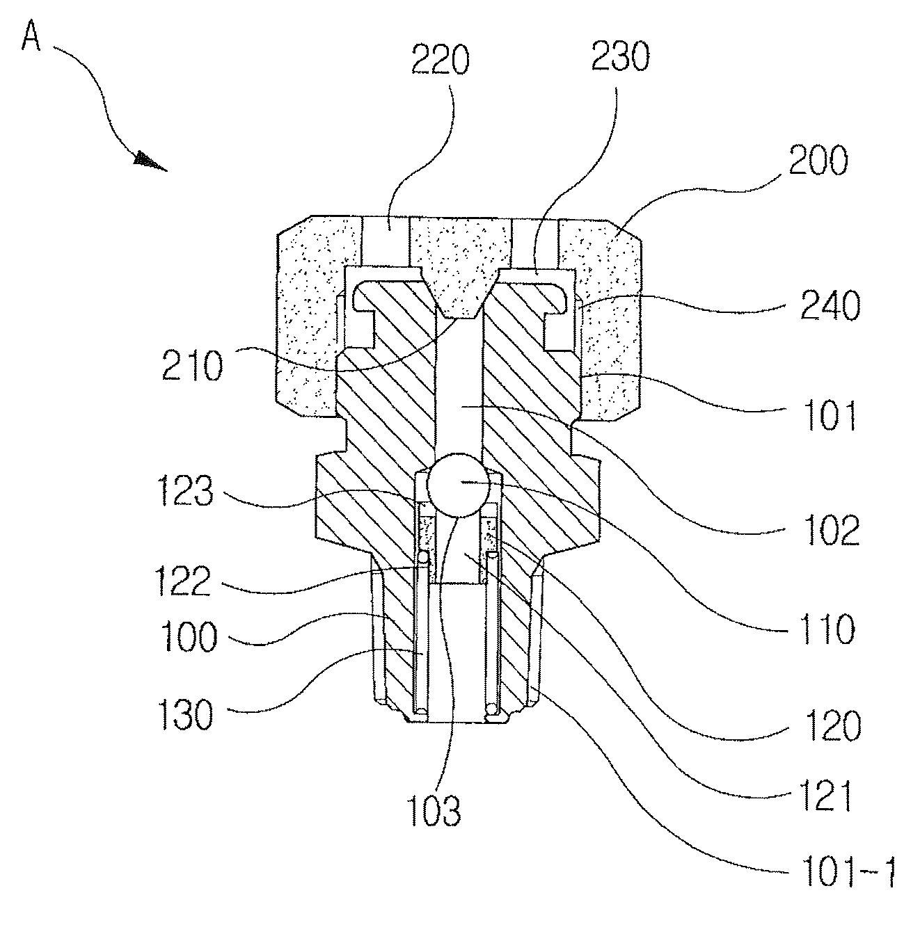
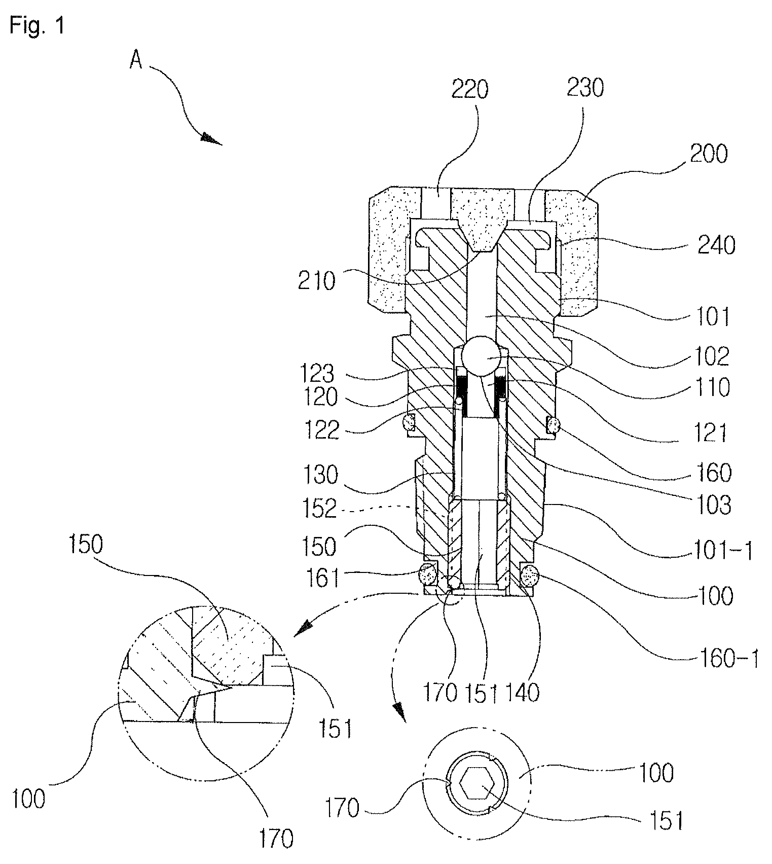
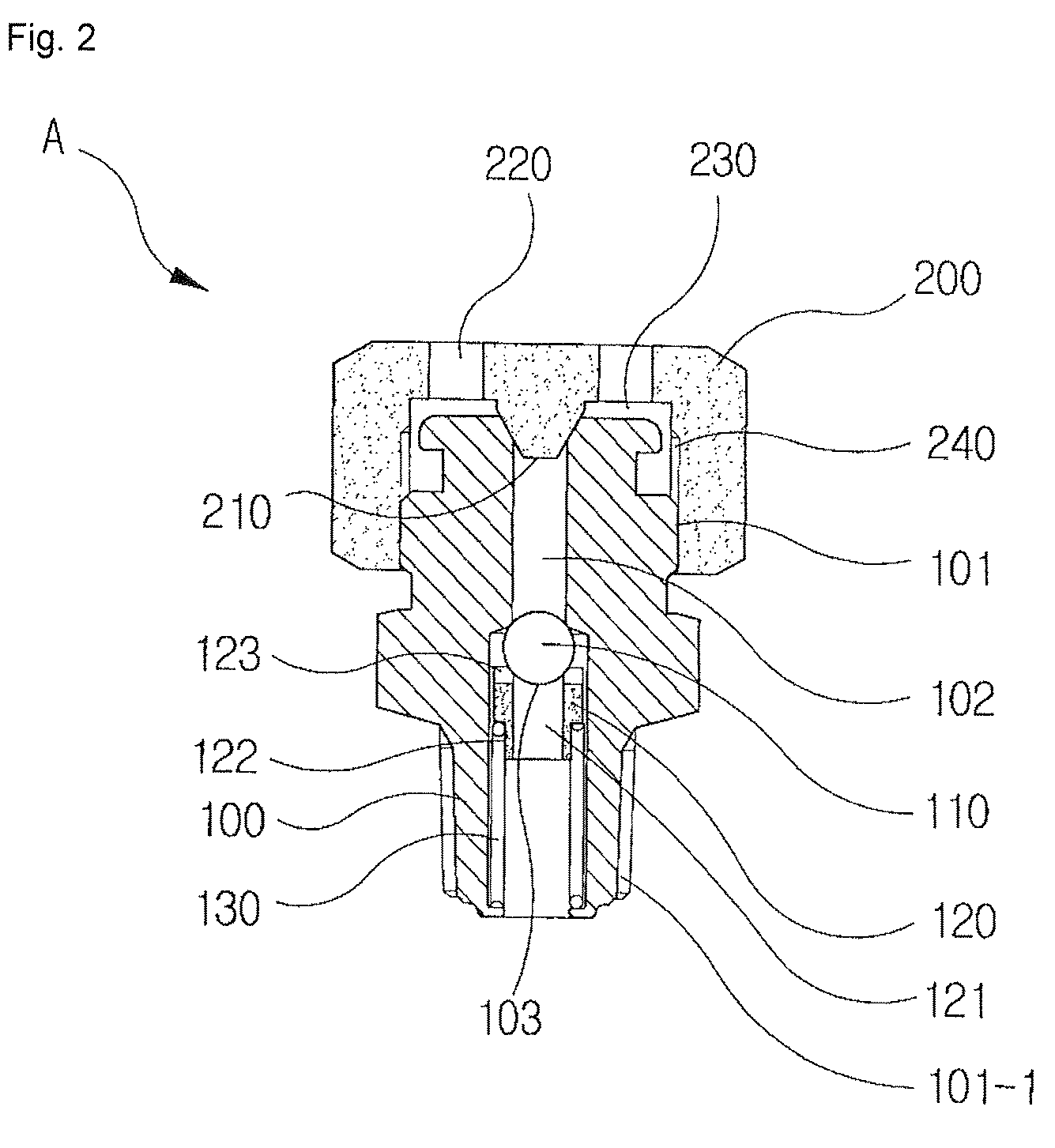
[0021]A sealant fitting A of the present invention includes a sealant body 100 and a vent cap 200, wherein the sealant body has a cap coupling screw part 104 disposed on an outer upper end of the sealant body, a valve coupling taper screw part 101-1 disposed on an outer lower end of the sealant body, a sealant injection hole 102 disposed on its inner upper end and a ball installation groove 103 disposed on its inner lower end, the ball installation groove 103 has a ball 110 while a ball seat 120 and a coil spring 130 are sequentially disposed downward from the ball installation groove, the vent cap has a protrusion 210 for discharging an inner air and additionally blocking the sealant injection hole 102 and one or more punched vent groove 220, the vent cap is coupled to the cap coupling screw part 101 of the sealant body 100, and the sealant fitting further includes:

[0022]a spring cou...


PUM

PropertyMeasurementUnit
diameteraaaaaaaaaa
mechanical propertyaaaaaaaaaa
temperatureaaaaaaaaaa

Abstract

A valve sealant fitting includes a spring coupling unit having an internal screw thread for coupling unit assembly below the ball installation groove of the sealant body, the internal screw thread having a hexagonal groove for preventing a downward separation of the coil spring, allowing a fluid to flow and facilitating fastening and releasing of the screw, and having an external screw thread at an outer circumference of the spring coupling unit, and outer sealing O-rings disposed in O-ring installation grooves formed on respective upper and lower positions of the valve coupling taper screw part formed on the outer lower side of the sealant body.

Description

TECHNICAL FIELD[0001]The present invention relates to a valve sealant fitting and a method of manufacturing the same, and in particular, to a valve sealant fitting of high quality and a method of manufacturing the same, which not only allows a sealant to be rapidly and easily injected but also prevents a leakage of the sealant, which result in a more facilitated manufacturing process with reduced costs and a superior mechanical quality.BACKGROUND ART[0002]When a leakage typically occurs on a high pressure value or a low temperature valve mounted in a pipe line for gas or fluid (e.g., petrochemical material or the like) due to abrasion or scratch of a sealing portion within the valve, emergency measures are taken by mounting three or four sealant fittings in one valve to allow not only a sealant for fluid interception to be rapidly injected but also a lubricant for keeping smooth operations and functions of the valve to be filled / injected if necessary.[0003]In the meantime, according...

Claims


Application Information

Patent Timeline
Patent Type & Authority Patents(United States)
IPC IPC(8): B23P17/00
CPCF16K15/044Y10T29/49314Y10T29/49298Y10T29/49304Y10T137/7927F16K1/36F16K25/005F16K27/0209F16K27/0245
Inventor KIM, DO AHAN, SEONG CHEOL
Owner KIM DO A
Why Eureka
Try Eureka