Control apparatus for controlling on-vehicle starter for starting engine
a technology of control apparatus and starter, which is applied in the direction of engine starter, machine/engine, instruments, etc., can solve the problems of shortening the life of the starter, affecting and consuming battery power, so as to enhance the durability of the starter and significantly increase the load of the battery
- Summary
- Abstract
- Description
- Claims
- Application Information
AI Technical Summary
Benefits of technology
Problems solved by technology
Method used
Image

Examples
first embodiment
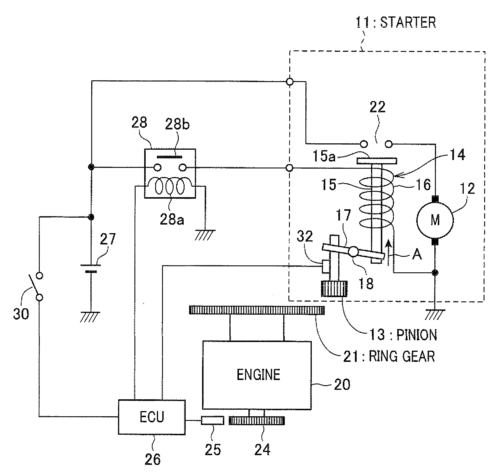
[0036]With reference to FIGS. 1 to 4, hereinafter will be described a first embodiment of the present invention. First, with reference to FIG. 1, a configuration of an automatic stop / restart system (idle stop system) is described as follows. The starter 11 is what is called pinion push out type starter including a motor section 12, a pinion 13 driven by the motor section 12 to allow the pinion 13 to rotate and a pinion actuator 14 used for pushing out the pinion 13.
[0037]The pinion 13 is connected to a rotary shaft of a reduction mechanism (not shown) of the motor section 12 via a one-way clutch (not shown). The pinion 13 is configured to be movable in an axial direction of the rotary shaft. The pinion actuator 14 includes a plunger 15 and a plunger solenoid 16 and is configured to push out the pinion 13 when the engine starts. The plunger 15 is connected to the one-way clutch of the pinion 13 via the lever 17. The plunger 15 is suctioned towards a direction A indicated by the arrow...
second embodiment
[0058]With reference to FIGS. 5 and 6, hereinafter will be described a second embodiment of the present invention. According to the above-described first embodiment, to detect the state where the pinion 13 of the starter 11 has been driven by the ring gear 21 of the engine 20 side while the starter 11 is powered, the torque sensor 32 is arranged. However, according to a second embodiment of the present invention as shown in FIGS. 5 and 6, a pinion rotational rate sensor 33 to detect a rotational rate of the pinion of the starter 11 is provided (torque sensor 32 in the first embodiment is not provided).
[0059]According to the second embodiment, while the starter 11 is powered ON, the ECU 26 determines whether or not the pinion rotational rate detected by the pinion rotational rate sensor reaches the no-load rotational rate or more. When the pinion rotational rate reaches the no-load rotational rate or more, the ECU 26 determines that the pinion 13 has been driven by the ring gear 21. ...
third embodiment
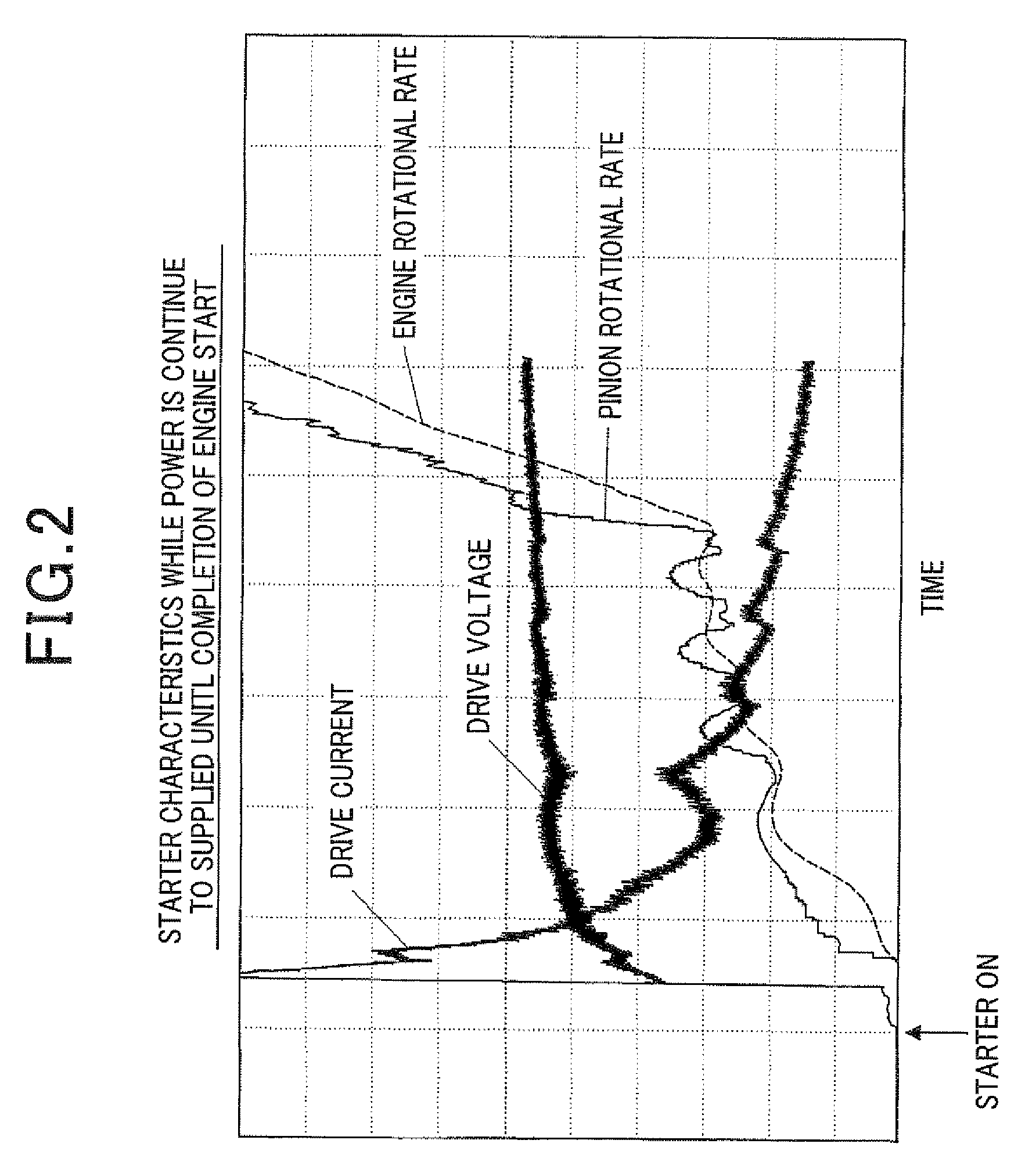
[0065]With reference to FIGS. 7 and 8, hereinafter will be described a third embodiment of the present invention. As shown in FIGS. 7 and 8, a current sensor 34 is arranged to detect drive current of the starter 11 (drive current of the motor section 12). In this configuration, it is determined that the pinion 13 of the starter 11 has been driven by the ring gear 21 when the drive current of the starter 11 reaches a predetermined value or less whereby the ECU 26 stops supplying power to the starter 11.
[0066]As shown in FIG. 2, while the engine is starting, load (torque) of the starter 11 decreases when the rotational rate of the engine rotation rate increases so that the drive current of the starter 11 decreases. Accordingly, it is determined that the pinion 13 has been driven by the ring gear 21 when the drive current of the starter 11 reaches the predetermined value or less.
[0067]Alternatively, it is determined that the pinion 13 has been driven by the ring gear 21 when the change...
PUM
 Abstract
Description
Claims
Application Information
 - R&D
- Intellectual Property
- Life Sciences
- Materials
- Tech Scout
- Unparalleled Data Quality
- Higher Quality Content
- 60% Fewer Hallucinations
Browse by: Latest US Patents, China's latest patents, Technical Efficacy Thesaurus, Application Domain, Technology Topic, Popular Technical Reports.
© 2025 PatSnap. All rights reserved.Legal|Privacy policy|Modern Slavery Act Transparency Statement|Sitemap|About US| Contact US: help@patsnap.com