Heat generator group with jet pump flow circuit control

a technology of flow circuit and heat generator, which is applied in the direction of air heaters, domestic heating details, space heating and ventilation details, etc., can solve the problems of at least then problems, become convenient to integrate several heat sources, etc., and achieve cost-optimized overall operation, maximum energy efficiency, and optimal energy generation

Inactive Publication Date: 2011-08-25
BALZ HELMUT
View PDF19 Cites 7 Cited by
  • Summary
  • Abstract
  • Description
  • Claims
  • Application Information

AI Technical Summary

Benefits of technology

[0011]If the heat source is, for example, an oven operated by a solid or a liquid fuel, or a boiler, the control arrangement may first set the jet pump of the respective heat source to a predetermined minimum setting in order to maintain in a start-up state a minimum circulation flow volume as required by the manufacturer. When the respective oven or boiler has then reached its operating temperature the jet pump controls the volume flow in a temperature-dependent manner for optimal energy generation. It can adjust the volume flow and the respective inlet and outlet temperatures in such a way that a maximum energy efficiency is obtained in the respective oven or boiler.
[0012]Furthermore, with an appropriate setting of the various jet pumps a volume flow distribution between the individual heat sources can be achieved which results in a cost-optimized overall operation. For example, the extraction of solar energy may be given preference over the generation of energy by combustion of fuel. If, for example, the solar installation supplies a large part of the required heat, but a small amount of additional heat is required, the generation of additional heat by fuel is reduced to a minimum and this is also chosen if as a result the furnace or boiler will then operate at or somewhat lower efficiency. Generally, however, by an appropriate jet pump control the temperature spread between inlet and outlet of the respective furnace or boiler can still be adjusted to an optimum value. In this way, the operation of the individual heat sources with the jet pump and the admixing of heat carrier flow volume to the return line, the flow through the furnace or boiler and the inlet temperature can be independently adjusted at least within limits. In this way, both objects, that is the optimization of the efficiency at the individual heat sources and an optimum utilization of heat generated without cost (for example solar energy), can be achieved.

Problems solved by technology

Increasingly, however, it becomes expedient to integrate several heat sources into the heat utilization installations.
This may become at least then problematic when the individual heat sources have very different properties.

Method used


Image

  • Heat generator group with jet pump flow circuit control
  • Heat generator group with jet pump flow circuit control

Examples


Embodiment Construction

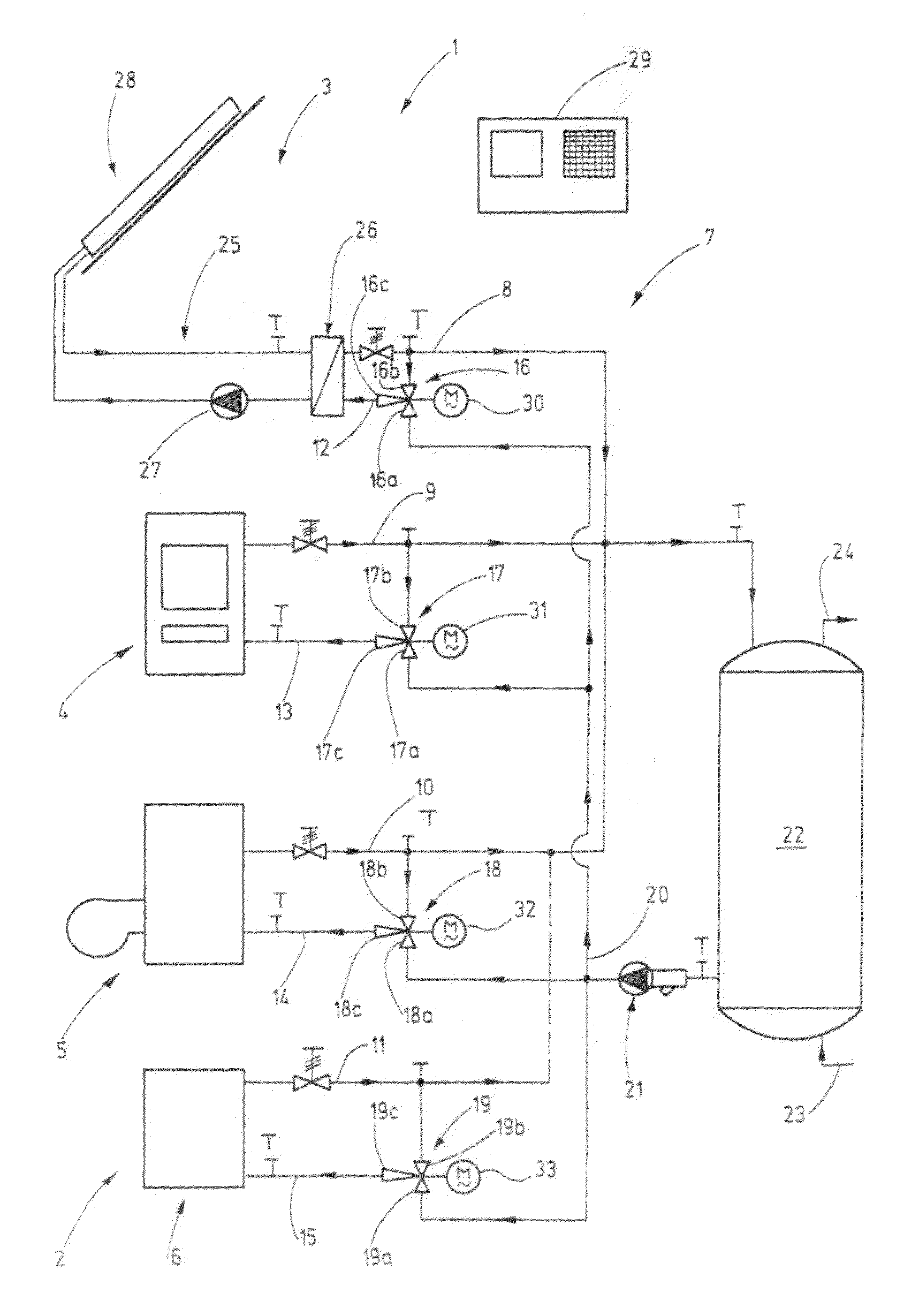
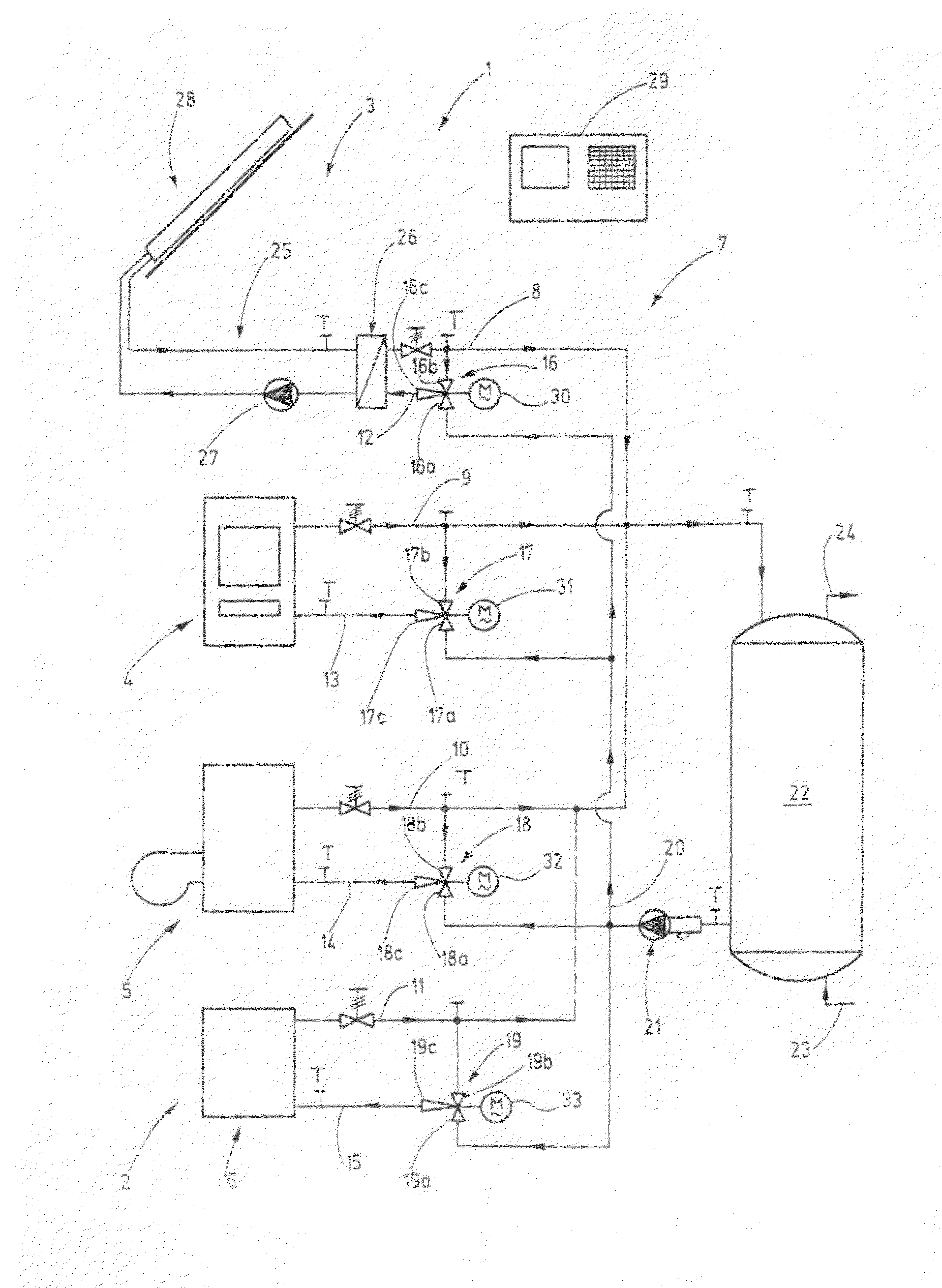
[0015]The FIGURE shows a heat utilization installation or plant 1 provided for example for heating a building. The heat utilization installation 1 is shown only in part, particularly with respect to the components for the generation of the heat. Heat consumers such as for example radiators, floor heating systems, hot water storage devices or similar are not shown.

[0016]The heat utilization installation 1 utilizes several, preferably different but, if expedient, also same type heat sources 2, including for example a thermal solar heat collector system 3, a furnace 4 for solid fuels, a boiler suitable for fluid fuels such as for example a gas furnace or an oil furnace or another heat source 6. The other heat source may be for example a geothermal plant, an arrangement for utilizing the waste heat of a fuel cell, a heat generating engine operating in connection with the heat utilization system or a heat storage device.

[0017]For networking all the heat sources 2 a heat transport circuit...


PUM


Abstract

In the heat utilization installation (1) according to the invention several heat sources (2) are included which are provided each with a jet pump (16), (17), (18), (19). The heat sources (2) are connected to a heat carrier circuit system (7) which includes a single, central circulating pump or circulating pump unit (20). The individual jet pumps (16) to (19) are so controlled for the respective heat sources (2), the required operating temperatures with respect to temperature difference between the outlet and inlet and the flow volume are maintained or achieved. With the possibility of independent control of the flow volumes at the various heat sources (2), uniform fluid temperatures as required for a buffer store (22) or heat consumers can be maintained.

Description

CROSS-REFERENCE TO RELATED APPLICATION[0001]This application claims the priority of German Application No. 10 2010 009 081.6-34 filed Feb. 24, 2010.BACKGROUND OF THE INVENTION[0002]The invention resides in a heat utilization installation with at least two heat sources of the same or of a different type.[0003]Heat supply installations are known wherein several heat consumers are supplied with heat from a single heat source. DE 198 59 364 C2,for example, discloses a remote heat utilization system in which the heat supply to the individual heat consumers is apportioned by jet pumps. They utilize the pressure difference present in the remote heat supply system between the supply line and the return line for the circulation of the heat carrier fluid through the consumer circuits so that no electrical circulation pump is needed for circulating the heat carrying fluid.[0004]Increasingly, however, it becomes expedient to integrate several heat sources into the heat utilization installations...

Claims


Application Information

Patent Timeline
Patent Type & Authority Applications(United States)
IPC IPC(8): F24J2/46F24J2/04F24H3/02F24J3/08F24J2/40F24H3/12F24S90/00
CPCF24D12/02F24D19/1015F24D2200/04F24D2200/06F24D2200/10Y02B30/14F24D2200/12F24D2200/14Y02B10/20Y02B10/40Y02B10/70F24D2200/11Y02B30/00
Inventor THOMA, HANS GUNTHER
Owner BALZ HELMUT
Why Eureka
Try Eureka