Plasma Lamp with Dielectric Waveguide Body Having Shaped Configuration

Inactive Publication Date: 2011-08-25
TOPANGA USA
View PDF28 Cites 5 Cited by
  • Summary
  • Abstract
  • Description
  • Claims
  • Application Information

AI Technical Summary

Benefits of technology

[0012]The present invention provides a dielectric support structure in which the bulb sits in. the bulb is supported in the structure through a protrusion that extends from the inner cavity of the support structure and makes contact around the periphery of the bulb. The protrusion extends from the support structure in a curved manner, thereby reducing the electric field that is generated at such protrusion. By reducing the electric field, the plasma is generated in the bulb at lower RF power levels, thereby increasing the lumens per watt characteristic of the lamp apparatus. Of course, there can be other variations, modifications, and alternatives.
[0013]Benefits are achieved over pre-existing techniques using the present invention. In a specific embodiment, the present invention provides a method and device having configurations of input, output, and feedback coupling elements that provide for electromagnetic coupling to the bulb whose power transfer and frequency resonance characteristics that are largely dependent upon a waveguide body having at least two materials. In a preferred embodiment, the present invention provides a method and configurations with an arrangement that provides for improved manufacturability as well as design flexibility. Other embodiments may include integrated assemblies of the output coupling element and bulb that function in a complementary manner with the present coupling element configurations and related methods for street lighting applications. In a specific embodiment, the present method and resulting structure are relatively simple and cost effective to manufacture for commercial applications. In a preferred embodiment, the invention provides a resulting device and method having a higher efficiency using rounded spatial features within one or more portions of the resonator structure to reduce electric fields and the like. Depending upon the embodiment, one or more of these benefits may be achieved. These and other benefits may be described throughout the present specification and more particularly below.

Problems solved by technology

Although highly successful, the Edison bulb consumed much energy and was generally inefficient.
Fluorescent lighting is much more efficient than incandescent lighting, but often has a higher initial cost.
Although somewhat successful, the electrode-less lamp still had many limitations.
As an example, electrode-less lamps have not been successfully deployed.
Additionally, the conventional lamp also uses a high frequency and has a relatively large size, which is often cumbersome and difficult to manufacture and use.

Method used


Image

  • Plasma Lamp with Dielectric Waveguide Body Having Shaped Configuration
  • Plasma Lamp with Dielectric Waveguide Body Having Shaped Configuration
  • Plasma Lamp with Dielectric Waveguide Body Having Shaped Configuration

Examples


Embodiment Construction

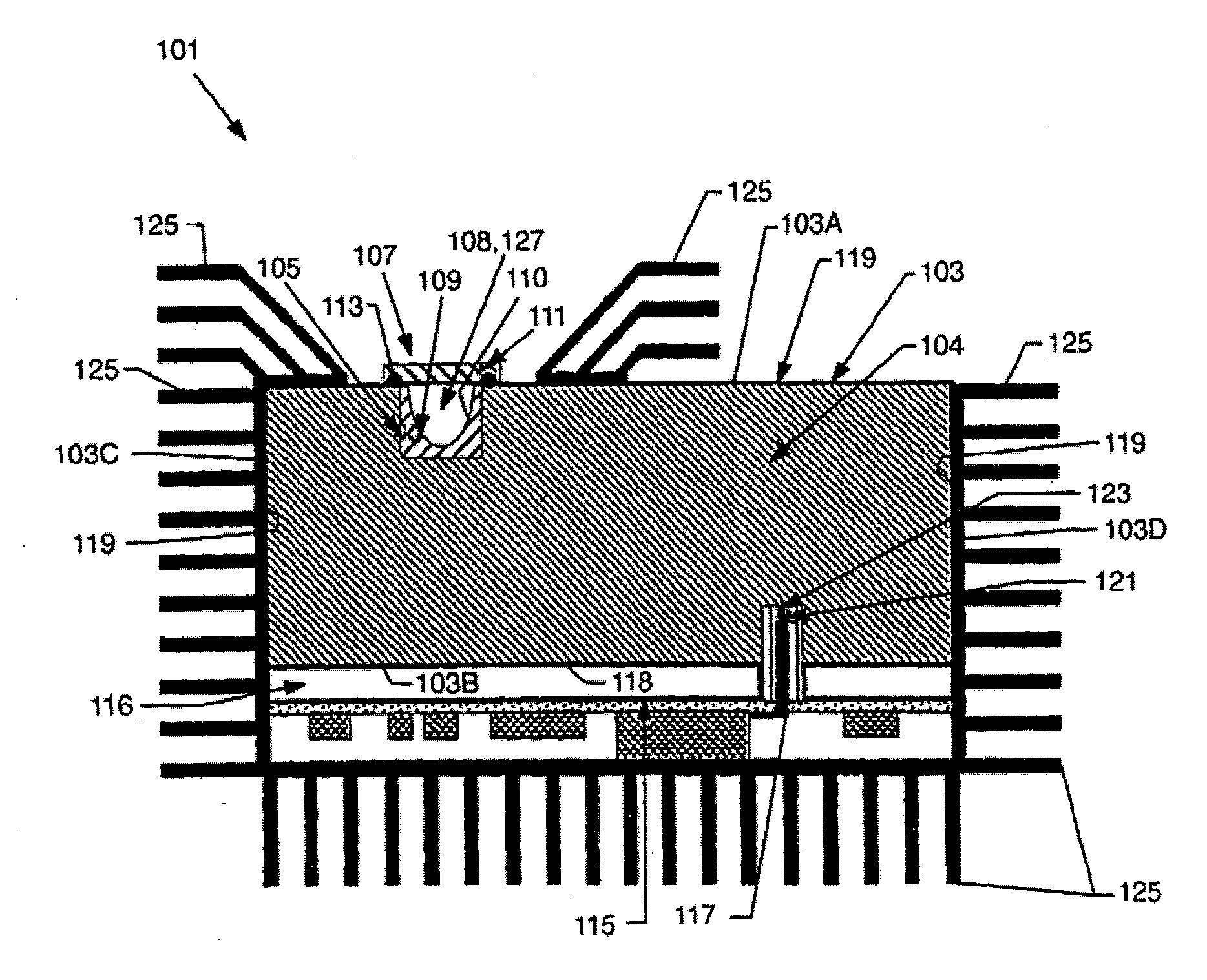
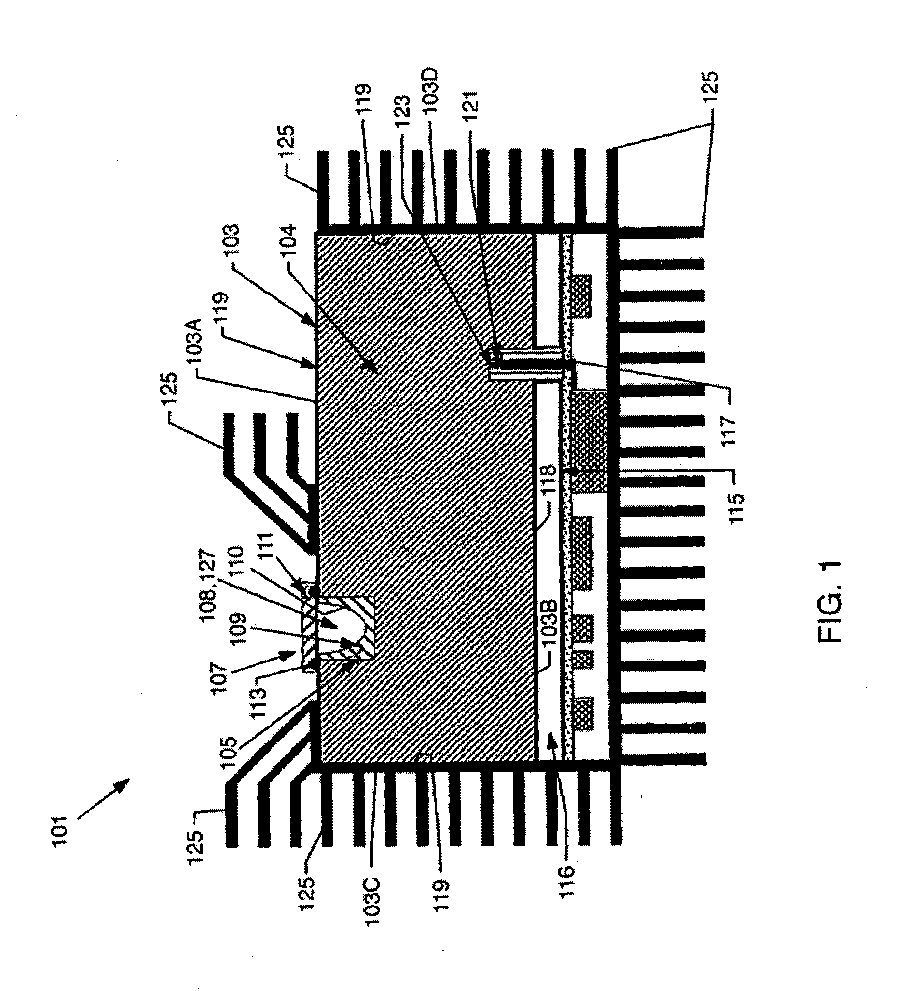
[0025]According to the present invention, techniques for lighting are provided. In particular, the present invention provides a method and device using a plasma lighting device having a dielectric waveguide body having a shaped configuration. Merely by way of example, the invention can be applied to a variety of applications including a warehouse lamp, stadium lamp, lamps in small and large buildings, and other applications.

[0026]According to the present invention, techniques for lighting are provided. In particular, the present invention provides a method and device using a plasma lighting device having a dielectric waveguide of a dielectric constant of less than 2. More particularly, the present invention provides a method and apparatus having a plasma lighting device using a ceramic resonator structure of a dielectric constant of less than 2. Merely by way of example, the invention can be applied to a variety of applications including a warehouse lamp, stadium lamp, lamps in smal...


PUM


Abstract

A plasma lamp apparatus that includes an improved bulb support assembly to increase the lumens per watt output of the apparatus. The bulb support assembly includes a support structure that forms a cavity for receiving the bulb. The bulb is supported within the cavity though a protrusion that extends out from the support structure in a curved manner. By created a curved protrusion, the electric field within the resonating structure of the lamp apparatus is lowered. Lowering the electric field leads to lower resonating frequencies of the resonating structure. In lowering the resonating frequency, the resonating structure is driven to resonate at lower power levels, thereby increasing the lumens per watt output of the lamp apparatus.

Description

CROSS-REFERENCES TO RELATED APPLICATIONS[0001]NOT APPLICABLESTATEMENT AS TO RIGHTS TO INVENTIONS MADE UNDER FEDERALLY SPONSORED RESEARCH OR DEVELOPMENT[0002]NOT APPLICABLEREFERENCE TO A “SEQUENCE LISTING,” A TABLE, OR A COMPUTER PROGRAM LISTING APPENDIX SUBMITTED ON A COMPACT DISK[0003]NOT APPLICABLEBACKGROUND OF THE INVENTION[0004]The present invention relates generally to lighting techniques. In particular, the present invention provides a method and device using a plasma lighting device having a dielectric waveguide body having a shaped configuration. Merely by way of example, the invention can be applied to a variety of applications including a warehouse lamp, stadium lamp, lamps in small and large buildings, and other applications.[0005]From the early days, human beings have used a variety of techniques for lighting. Early humans relied on fire to light caves during hours of darkness. Fire often consumed wood for fuel. Wood fuel was soon replaced by candles, which were derived ...

Claims


Application Information

Patent Timeline
IPC IPC(8): H05B41/24H01J7/46
CPCH01J65/044
Inventor ESPIAU, FREDERICK M.MATLOUBIAN, MEHRAN
Owner TOPANGA USA
Why Eureka
Try Eureka