
Semiconductor device and manufacturing method therefor

a technology of semiconductors and semiconductors, applied in the direction of semiconductor devices, electrical devices, transistors, etc., can solve the problems of degrading the reading characteristics of reading data, poor programing and erasing characteristics, and interference with the miniaturization of memory cells, so as to achieve the effect of low resistance bit lines

Active Publication Date: 2010-11-02
MONTEREY RES LLC
View PDF16 Cites 0 Cited by
  • Summary
  • Abstract
  • Description
  • Claims
  • Application Information

AI Technical Summary

Benefits of technology

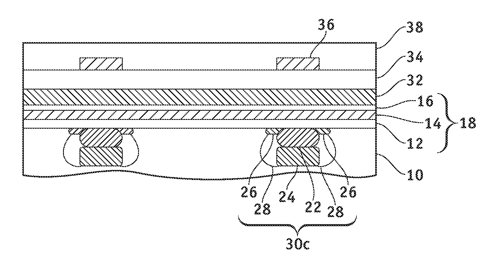
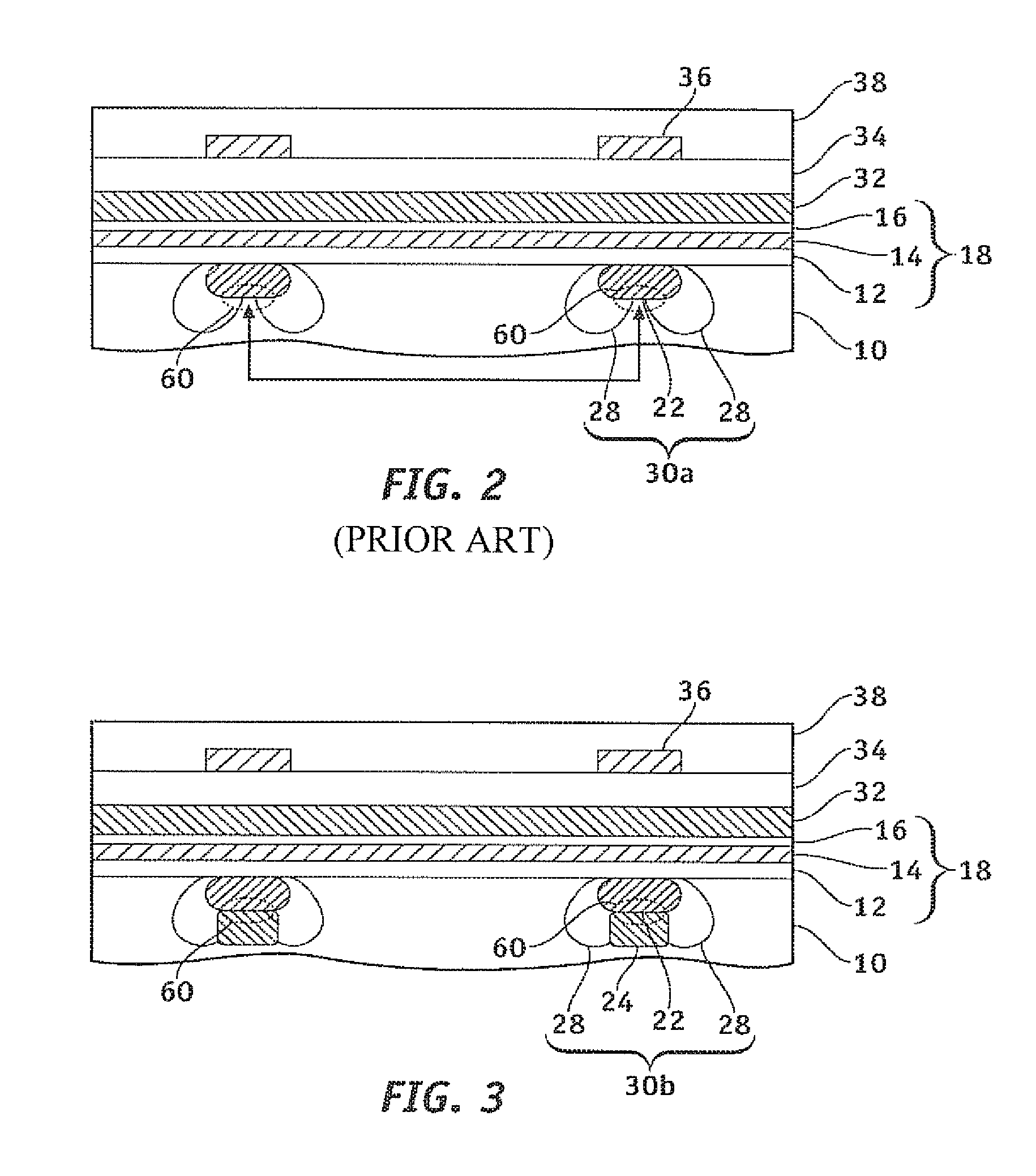
"The present invention provides a semiconductor device and a manufacturing method that can reduce the breakdown voltage between memory cells and allow for the formation of low-resistance bit lines. This is achieved by reducing the junction profile of the bottom portion of the high concentration diffusion region, which reduces the electric field even when high voltage is applied between the bit lines. The invention also includes the use of a mask layer to facilitate the formation of the high concentration diffusion region and the first low concentration diffusion region, and the use of side walls to accurately form the widths of the high concentration diffusion region and the first low concentration diffusion region. The technical effects of the invention include improved writing characteristics, reduced junction current, and improved source-drain breakdown voltage."

Problems solved by technology

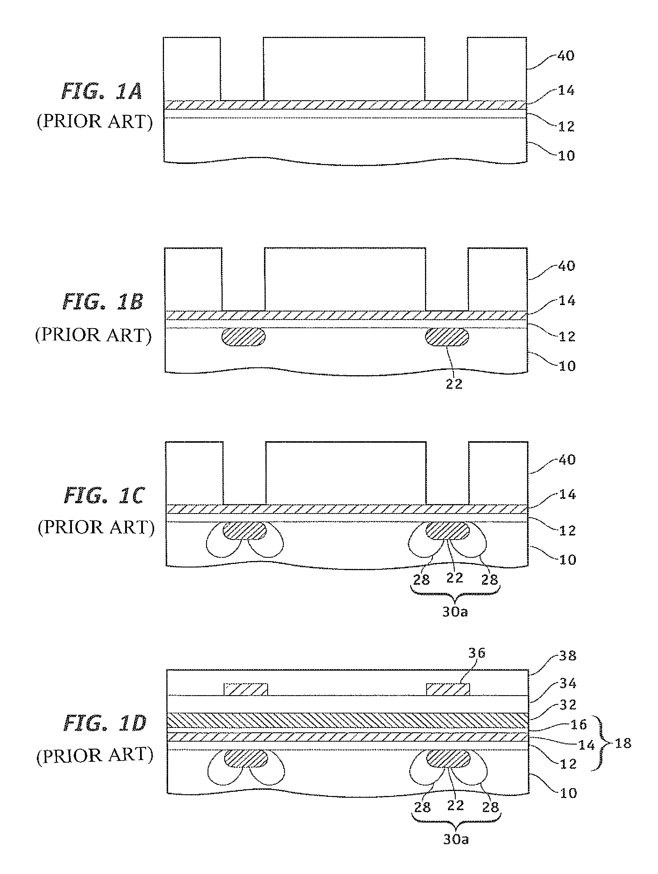
As a result, the programming and erasing characteristics become poor.
In addition, reading characteristics for reading data may also be degraded.
These issues interfere with the miniaturization of the memory cells.

Method used


Image

  • Semiconductor device and manufacturing method therefor
  • Semiconductor device and manufacturing method therefor
  • Semiconductor device and manufacturing method therefor

Examples


first embodiment

[0042]A first embodiment of the present invention is an example in which ion implantation is performed with a photoresist and a mask layer. FIGS. 4(a) through 4(c) are respective cross-sectional views of a word line in the horizontal direction of the bit line showing a manufacturing method in accordance with the first embodiment of the present invention. In FIG. 4(a), a tunnel oxide film 12 (silicon oxide film) is formed on a P-type silicon semiconductor substrate 10 (or a P-type region within the semiconductor substrate) using, for example, a thermal oxidization method, and a trap layer 14 (silicon nitride film) is formed using, for example, a chemical vapor deposition (CVD) method. A photoresist 40 is applied onto the trap layer 14, and an opening having a width of about 100 nm is formed using an ordinary exposure technique. In FIG. 4(b), an N-type first low concentration diffusion region 24 is formed by implanting arsenic in the semiconductor substrate 10 at, for example, an impl...

second embodiment

[0053]A semiconductor device in accordance with a second embodiment of the present invention is an example of a semiconductor device wherein the ion implantation is performed using an insulating film as the mask layer. FIGS. 5(a) through 5(d) are respective cross-sectional views of the word line in the width direction of the bit line showing a manufacturing method in accordance with the second embodiment of the present invention. Referring to FIG. 5(a), the tunnel oxide film 12 and the trap layer 14 are formed on the semiconductor substrate 10 as in accordance with the first embodiment. A silicon oxide film, for example, is formed on the trap layer 14 as a mask layer 42 using a CVD method. A photoresist 44 is applied and an opening having a width of about 100 nm is formed using an ordinary exposure technique. The mask layer 42 is then etched with the photoresist 44 as the mask.

[0054]In FIG. 5(b), the photoresist 44 is removed. The high concentration diffusion region 22 is formed by ...

third embodiment

[0061]A third embodiment is an example of a semiconductor device in which side walls are formed and ion implantation is performed using the insulating film as the mask layer. FIGS. 6(a) to 6(d) and FIGS. 7(a) to 7(c) are respective cross-sectional views of the word line in the horizontal direction of the bit line, showing a manufacturing method in accordance with the third embodiment of the present invention. In FIG. 6(a), the tunnel oxide film 12 and the trap layer 14 are formed on the semiconductor substrate 10, as in accordance with the second embodiment. A silicon oxide layer, for example, is formed on the trap layer 14 as the mask layer 42, using, for example, the CVD method. The photoresist 44 is applied and an opening having a width of about 100 nm is formed using an ordinary exposure technique. The mask layer 42 is then etched with the photoresist 44 as the mask.

[0062]In FIG. 6(b), the photoresist 44 is removed and the high concentration diffusion region 22 is formed with th...


PUM


Abstract

There is provided a semiconductor device including a semiconductor substrate (10), a high concentration diffusion region (22) formed within the semiconductor substrate (10), a first low concentration diffusion region (24) that has a lower impurity concentration than the high concentration diffusion region (22) and is provided under the high concentration diffusion region (22), and a bit line (30) that includes the high concentration diffusion region (22) and the first low concentration diffusion region (24) and serves as a source region and a drain region, and a manufacturing method therefor. Reduction of source-drain breakdown voltage of the transistor is suppressed, and a low-resistance bit line can be formed. Thus, a semiconductor device that can miniaturize memory cells and a manufacturing method therefor can be provided.

Description

CROSS-REFERENCES TO RELATED APPLICATIONS[0001]This is a continuation of International Application No. PCT / JP2005 / 008057 filed Apr. 27, 2005, which was not published in English under PCT Article 21(2).BACKGROUND OF THE INVENTION[0002]1. Field of the Invention[0003]The present invention relates to a semiconductor device and a manufacturing method therefor. In particular, the present invention relates to a semiconductor device having a bit line that serves as a source region and a drain region and is buried in a semiconductor substrate.[0004]2. Description of the Related Art[0005]In recent years, non-volatile memory semiconductor devices wherein data can be overwritten are widely used. In the technical field of such non-volatile memories, technological developments are being made to miniaturize memory cells for high storage capacity. For example, there are metal oxide nitride oxide silicon (MONOS)-type Flash memories and silicon oxide nitride oxide silicon (SONOS)-type Flash memories i...

Claims


Application Information

Patent Timeline
Patent Type & Authority Patents(United States)
IPC IPC(8): H01L29/792
CPCH01L27/115H01L27/11568Y10S257/903H10B43/30H10B69/00
Inventor OKANISHI, MASATOMI
Owner MONTEREY RES LLC
Learn More