Traffic Control System and Method

a traffic control system and traffic control technology, applied in the direction of traffic control systems, road vehicles traffic control, instruments, etc., can solve the problems of conventional intersection controllers, inability to follow the progress of a particular vehicle in the presence of other vehicles, and high cost of multiple installation and disruption of traffi

Inactive Publication Date: 2011-08-25
TMT SERVICES & SUPPLIES
View PDF46 Cites 92 Cited by
  • Summary
  • Abstract
  • Description
  • Claims
  • Application Information

AI Technical Summary

Benefits of technology

It is an object of this invention to provide a traffic control system and method that overcomes, at least to some extent, the disadvantages associated with the prior

Problems solved by technology

The most significant two limitations of such presence detectors are that they can only sense a vehicle at the specific location where the detector is installed and even if a plurality of such detectors are installed along the road in an attempt to overcome that limitation, the progress of a particular vehicle cannot be followed in the presence of other vehicles.
Of course, separate detectors are required for at least each direction of approach to an intersection if any useful information is to be generated and the cost of multiple installations is expensive and disruptive to traffic during the installation procedure.
Added to this is the difficulty that such conventional intersection controllers, because of their basic detection drawbacks, use statistical traffic modelling in an attempt to infer the traffic conditions from the sparse data gathered from the presence detectors.
Such statistical modelling has a tendency to become inefficient under dense or slow moving traffic conditions.
The consequence of this is that when the intersection controller is required to optimize traffic flow most, such a controller performs at its worst.
The buttons and the circuits that they activate are, however, often worn out or defective, thereby not operating properly and making it increasingly difficu

Method used


Image

  • Traffic Control System and Method
  • Traffic Control System and Method
  • Traffic Control System and Method

Examples


Embodiment Construction

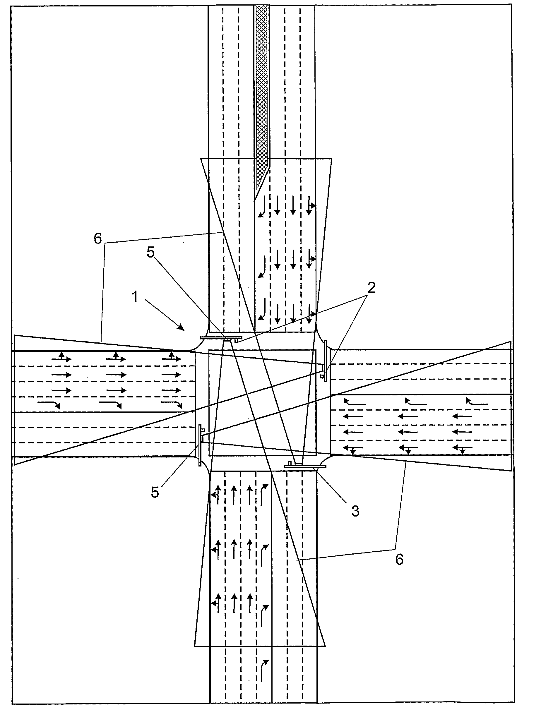
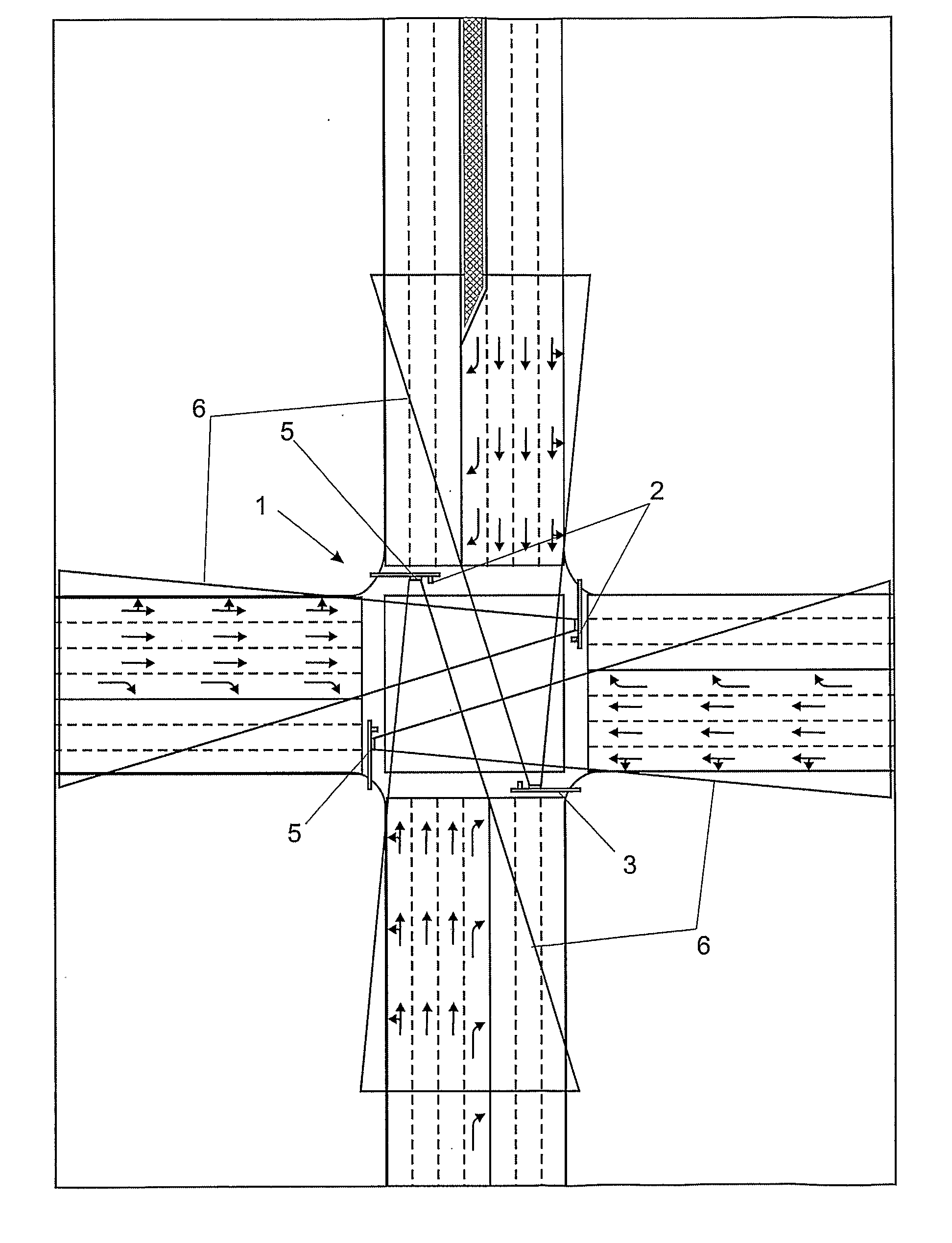
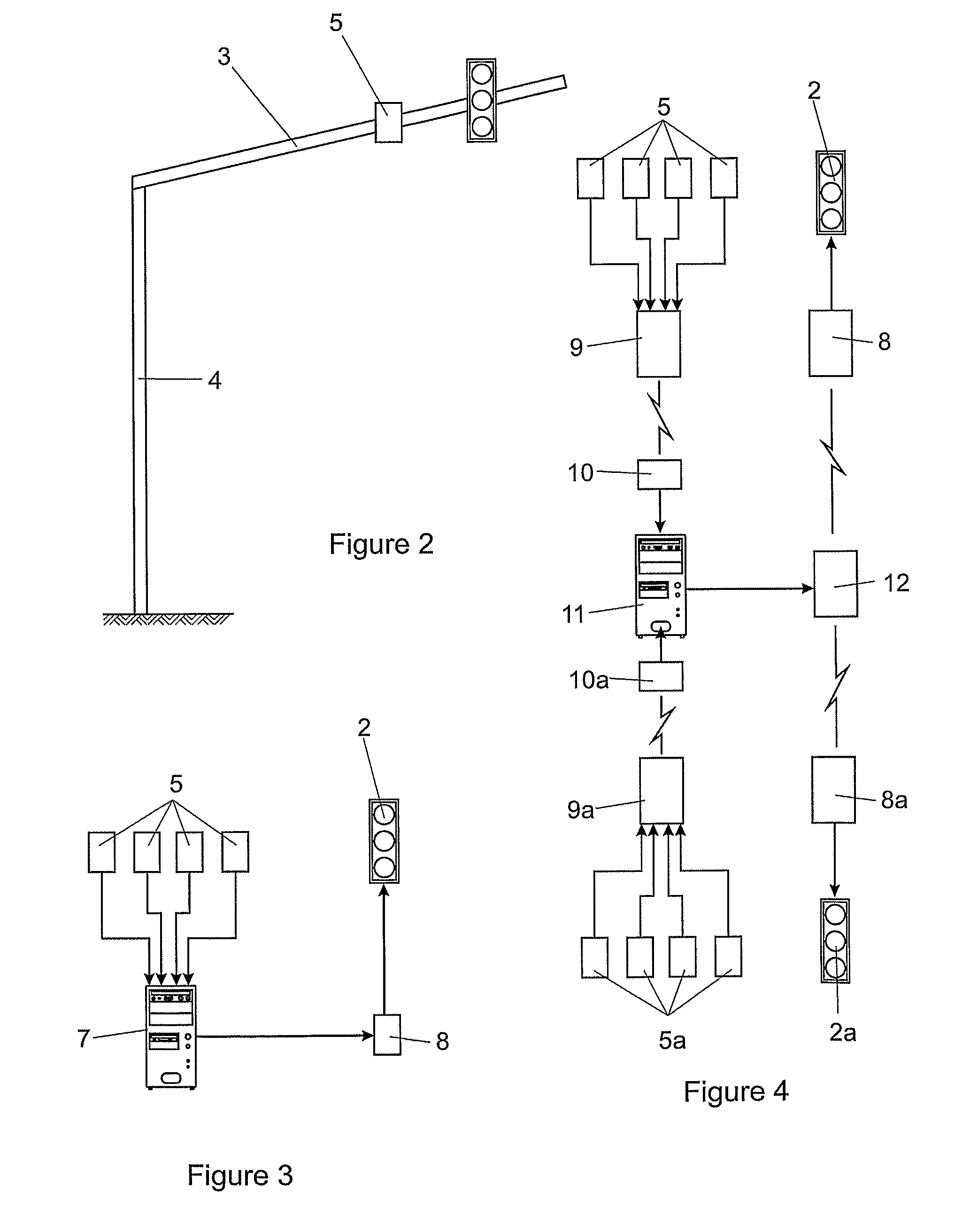
Referring firstly to FIGS. 1 and 2 of the accompanying drawings, one embodiment of the system according to the invention is applied to a simple crossroad intersection (1) controlled by the usual traffic lights (2) mounted, in this instance, on cantilever style of supports (3) carried at an upper region of a pole (4) offset laterally at one side of the road.

As provided by this invention, a multi-object radar traffic sensor (5), which in this instance is an FMCW radar, is mounted to the cantilever support (3) so that it has a predetermined range and detection area that is schematically illustrated by triangular areas indicated by numeral (6). The FMCW radar traffic sensors could be any suitable sensors and it is presently proposed to use commercially available radar sensors.

Typically, such radar sensors operate between 24 GHz and 76.5 GHz and may have up to 4 transmitting and receiving antennas. In the application of the present invention, it is essential that the position of each veh...


PUM


Abstract

A traffic control system is provided including an arrangement of traffic lights at a traffic intersection, and a radar sensor installed at the intersection such that its field and range of detection covers at least one approach to the intersection. The radar sensor is adapted to sense the presence of vehicles within a predetermined field of view and range. A controller for switching the traffic lights is operated by an electronic processor utilizing information developed from data inputted from the radar sensor. The radar sensor is a multi-object radar sensor capable of developing data from which the location, speed, acceleration or deceleration, and direction of travel of each vehicle within its field and range of detection can be derived.

Description

FIELD OF THE INVENTIONThis invention relates to a traffic control system and method for controlling the flow of traffic at intersections at which traffic lights are installed for the purpose of regulating the flow of traffic travelling in different directions. The term “traffic” as used in this specification mostly refers to vehicular traffic but, where appropriate, it should be widely construed to include pedestrian traffic as well.BACKGROUND TO THE INVENTIONMany conventional road traffic intersection controllers employ presence detectors to sense the presence of a vehicle. The most significant two limitations of such presence detectors are that they can only sense a vehicle at the specific location where the detector is installed and even if a plurality of such detectors are installed along the road in an attempt to overcome that limitation, the progress of a particular vehicle cannot be followed in the presence of other vehicles. Of course, separate detectors are required for at ...

Claims


Application Information

Patent Timeline
IPC IPC(8): G08G1/065G08G1/095
CPCG08G1/08G08G1/087G08G1/081
Inventor LAMPRECHT, GERHARDBENTLEY, BRENDON FARREN
Owner TMT SERVICES & SUPPLIES
Why Eureka
Try Eureka