
Multi-channel LED object detection system and method

a technology of led object detection and led light, applied in the field of object detection systems, can solve the problems of laser rangefinders that cannot detect objects, the amplitude of reflection received by detectors cannot reach the preset threshold, and the detector cannot detect objects

Active Publication Date: 2011-08-25
LEDDARTECH INC
View PDF100 Cites 79 Cited by
  • Summary
  • Abstract
  • Description
  • Claims
  • Application Information

AI Technical Summary

Benefits of technology

[0011]In one embodiment, the optical detector can include a plurality of optical sub-detectors, each having an individual narrow field-of-view. In one embodiment, the optical sub-detectors can detect simultaneously, in sequence or in combination. In one embodiment, their fields-of-view can overlap partly or completely or they can be adjacent to one another. In one embodiment, each optical sub-detector is able to receive and acquire a complete trace of the reflection for its own field-of-view, thereby creating a channel in the environment in which it is acquiring. The use of a plurality of sub-detectors allows a multichannel object detection. In one embodiment, the detection can be performed in one, multiple or all channels.

Problems solved by technology

Additionally, if some sections of the surface of an object illuminated by the laser beam have very poor reflectivity, the amplitude of the reflection received by the detector will not be enough to reach the preset threshold and the object will not be detected.
The laser rangefinder therefore presents reliability issues.
Some sections of the car which have very high reflectivity, such as the retro-reflector typically located at the back of the vehicles will have extremely high reflectivity toward the source but are very small in size and unlikely to receive the very collimated beam of the laser source.
There are therefore some drawbacks to the use of prior art systems, especially laser rangefinders.

Method used


Image

  • Multi-channel LED object detection system and method
  • Multi-channel LED object detection system and method
  • Multi-channel LED object detection system and method

Examples


Embodiment Construction

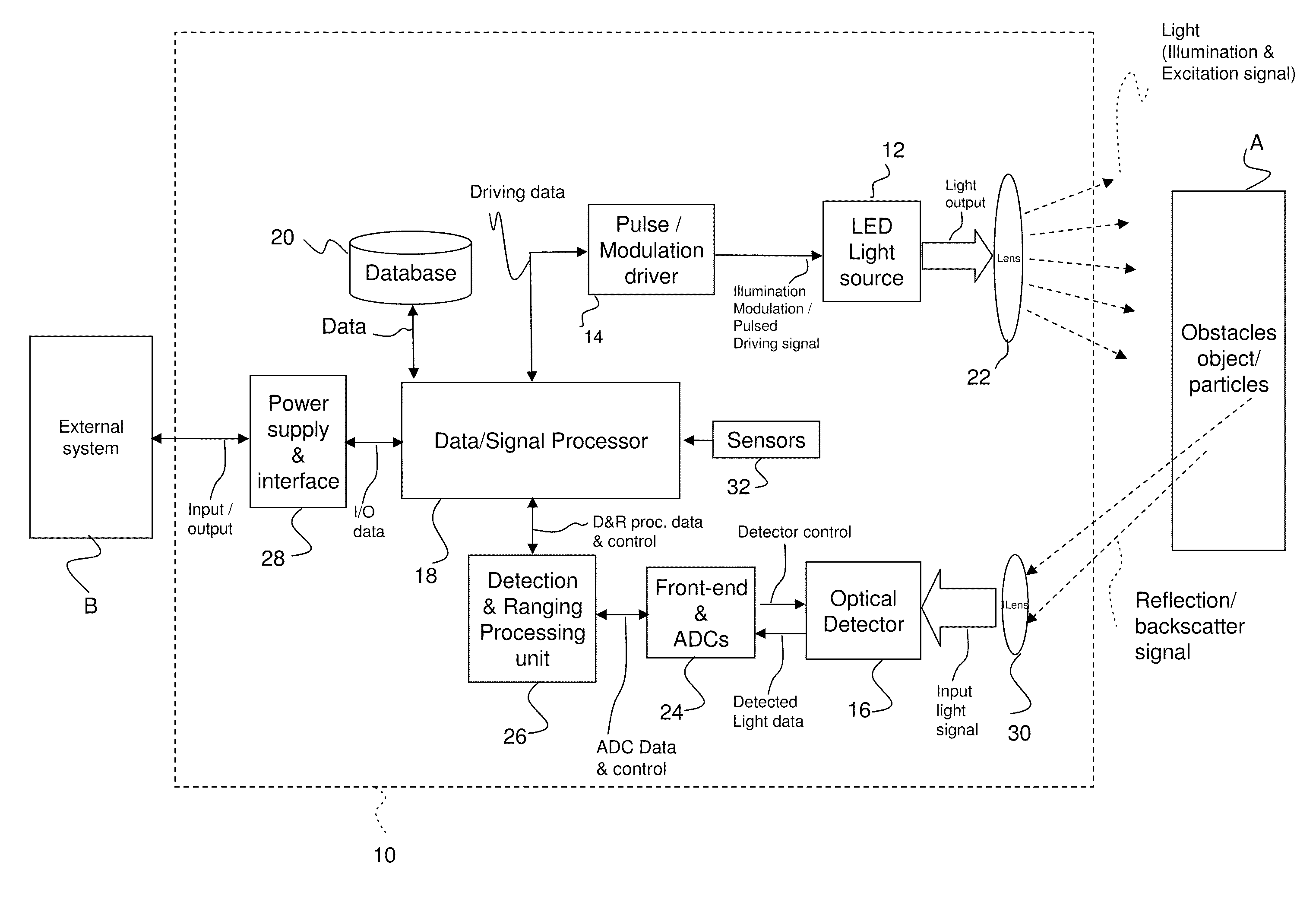
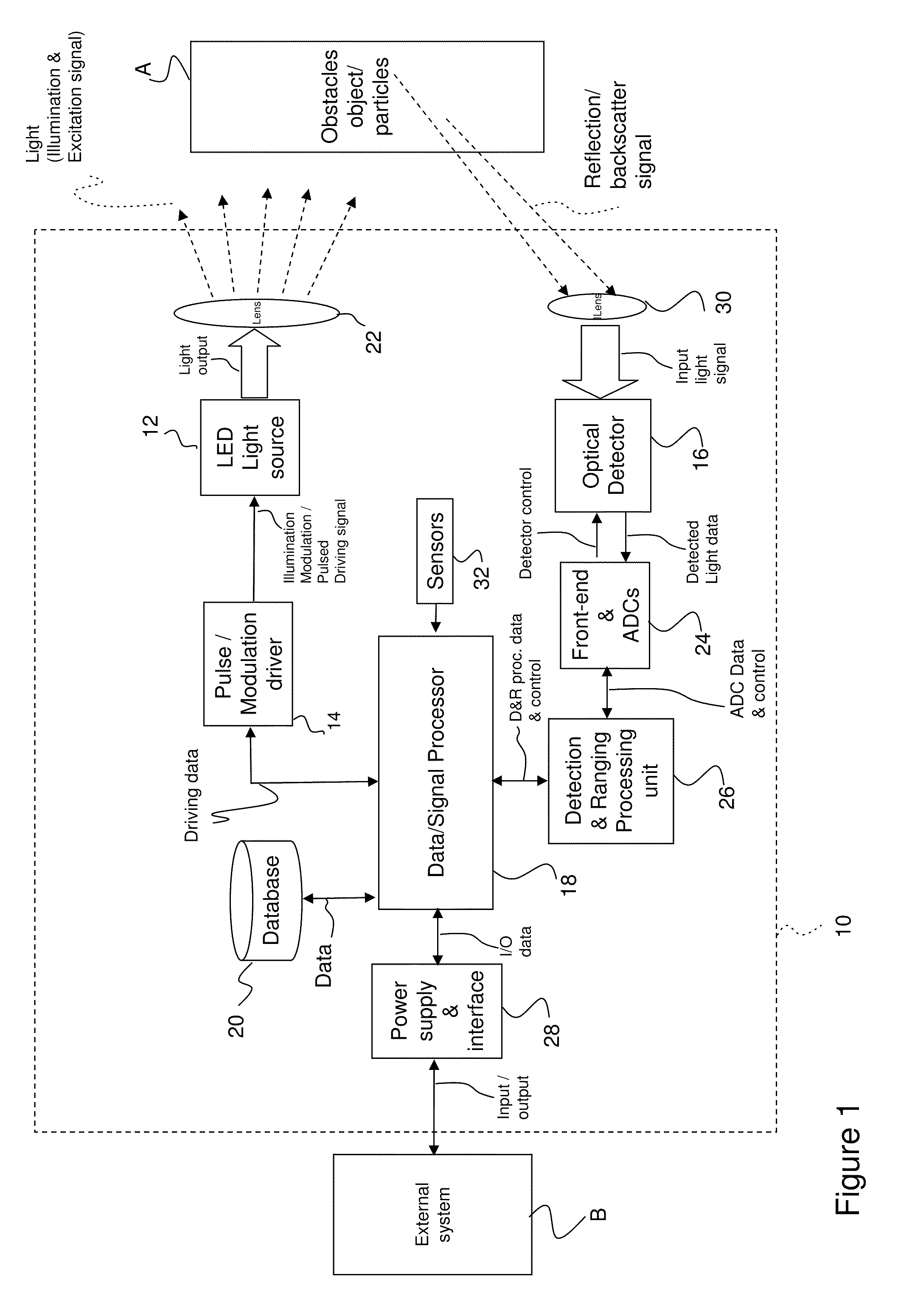
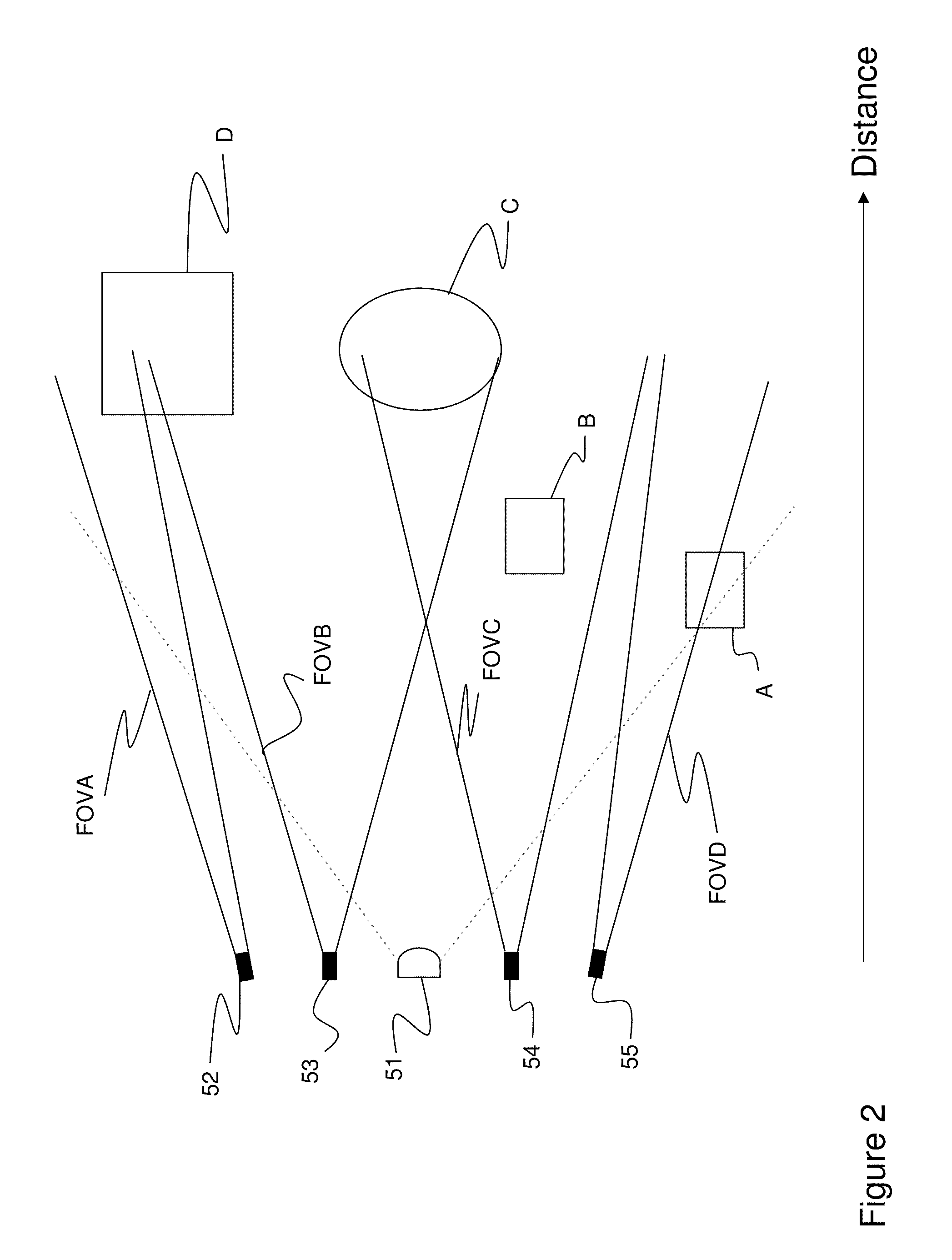
[0030]Referring to FIG. 1, a multichannel LED objet detecting system in accordance with one example embodiment is generally shown at 10.

[0031]The system 10 has at least one LED as a LED light source 12. The LED light source 12 can be invisible, visible or can include LEDs of both types.

[0032]The LED light source 12 is connected to a source controller 14 which is also referred to as the Pulse / Modulation driver 14, so as to be driven into producing illumination. In addition to emitting light, the system 10 performs the detection of objects when these objects are part of the environment / scene illuminated by the LED light source 12. The source controller 14 drives the LED light source 12 such that the emitted light can take the form of a light signal, for instance by way of amplitude-modulated or pulsed light emission, either in the visible or non-visible range of wavelengths.

[0033]All LEDs in a single module can be controlled by the same control signal or each one or a cluster of LEDs ...


PUM


Abstract

A method for detecting an object located in an environment and a multi-channel LED object detection system for detecting an object located in an environment are provided. The method includes providing a Light-Emitting-Diode (LED) light source having a wide field-of-illumination and orienting the LED light source for the wide field-of-illumination to encompass the width of the environment; providing an optical detector having a wide field-of-view and orienting the optical detector for the wide field-of-view to encompass the width of the environment, the optical detector having a plurality of sub-detectors, each having an individual narrow field-of-view, each individual narrow field-of-view creating a channel in the wide field-of-view; driving the LED light source into emitting light toward the environment, the width of the environment being illuminated by the light, the light having an emitted light waveform; receiving and acquiring an individual complete trace of a reflection / backscatter of the emitted light on the object in the environment at each sub-detector of the plurality, thereby combining the individual narrow field-of-view to create the wide field-of-view encompassing the width of the environment and thereby receiving and acquiring an individual complete trace for each channel; converting the acquired individual complete trace of the reflection / backscatter into an individual digital signal; and detecting and identifying at least one of a presence of an object in the environment, a position of the object in the environment, a distance between the object and the LED light source and a visibility in the environment, using the emitted light waveform and at least one of the individual digital signal.

Description

CROSS-REFERENCE TO RELATED APPLICATIONS[0001]This patent application is a continuation-in-part of U.S. patent application Ser. No. 11 / 612,678 filed on Dec. 19, 2006, now pending and allowed, which in turn claims priority on U.S. Provisional Patent Application No. 60 / 751,284, filed on Dec. 19, 2005, by Applicant, the specifications of which are hereby incorporated by reference.[0002]This patent application is also a continuation of U.S. patent application Ser. No. 12 / 664,744 filed on Dec. 15, 2009, now pending, which is a US national phase entry of PCT patent application no. PCT / CA2008 / 001161 filed on Jun. 18, 2008 which in turn claims priority on U.S. Provisional Patent Application No. 60 / 944,658, filed on Jun. 18, 2007, by Applicant, the specifications of which are hereby incorporated by reference.[0003]This patent application is also a continuation of U.S. patent application Ser. No. 12 / 664,753 filed on Dec. 15, 2009 , now pending, which is a US national phase entry of PCT patent ...

Claims


Application Information

Patent Timeline
IPC IPC(8): G01C3/08G01J1/44G01J5/10G01B11/14
CPCG01S7/4814G01S17/936G01S17/42G01S17/931
Inventor MIMEAULT, YVANCANTIN, DANIELGALLANT, PASCAL
Owner LEDDARTECH INC
Features
  • Generate Ideas
  • Intellectual Property
  • Life Sciences
  • Materials
  • Tech Scout
  • Unparalleled Data Quality
  • Higher Quality Content
  • 60% Fewer Hallucinations
Learn More