
Image scanning device capable of obtaining at high speed a scanned image of high quality and appropriate magnification, image scanning method, image formation apparatus, and recording medium

Active Publication Date: 2011-08-25
KONICA MINOLTA INC
View PDF4 Cites 12 Cited by
  • Summary
  • Abstract
  • Description
  • Claims
  • Application Information

AI Technical Summary

Benefits of technology

[0028]Particularly, the document feeder includes at least a first transportation roller arranged upstream of the first scanning position in the document transportation direction, and a second transportation roller arranged downstream o

Problems solved by technology

The transportation speed by the transportation rollers arranged at the upstream and downstream sides of the scanning position cannot be made to coincide with each other completely due to variation in the fabrication of the transportation rollers, wear of the transportation rollers due to usage, and the like.
Slacking in the document at the scanning position will lead to degradation in the resolution of the scanned image (occurrence of out-of-focus).
As a result, in the event of dual-side scanning, there is a problem that the magnification of the scanned image from the topside of the document read out by CCD 1120 will differ from the magnification of the scanned image from the back side of the document read out by CIS 1129.
Specifically, there is a problem that the magnification in the subscanning direction of the scanned image from the back side of the document will become smaller with respect to the magnification in the subscanning direction of the scanned image from the back side of the document.
The aforementioned Japanese Laid-Open Patent Publication No. 2006-115134 does not take into account the fact that the document transportation speed of a document by the transportation roller located at the downstream side in the transportation path is set higher than the transportation speed by the transportation roller located at the upstream side in the transportation path, and cannot address degradation in the resolution caused by slacking in a document at the scanning position.
Therefore, the timing control is complicated, and a particular hardware configuration to realize such control is required.
Furthermore, there is a problem of degradation in the image quality.
However, this system has the problem that the advantage of dual-side scanning for image reading at high speed is degraded since the data of the back side scanned image is temporarily stored in a memory, which had to be read out again to be subjected to image processing.

Method used


Image

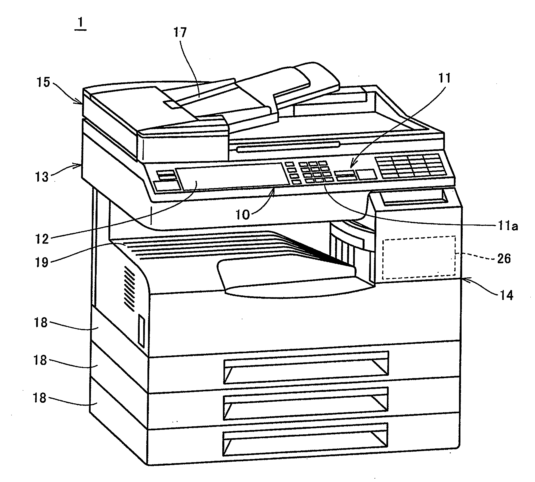
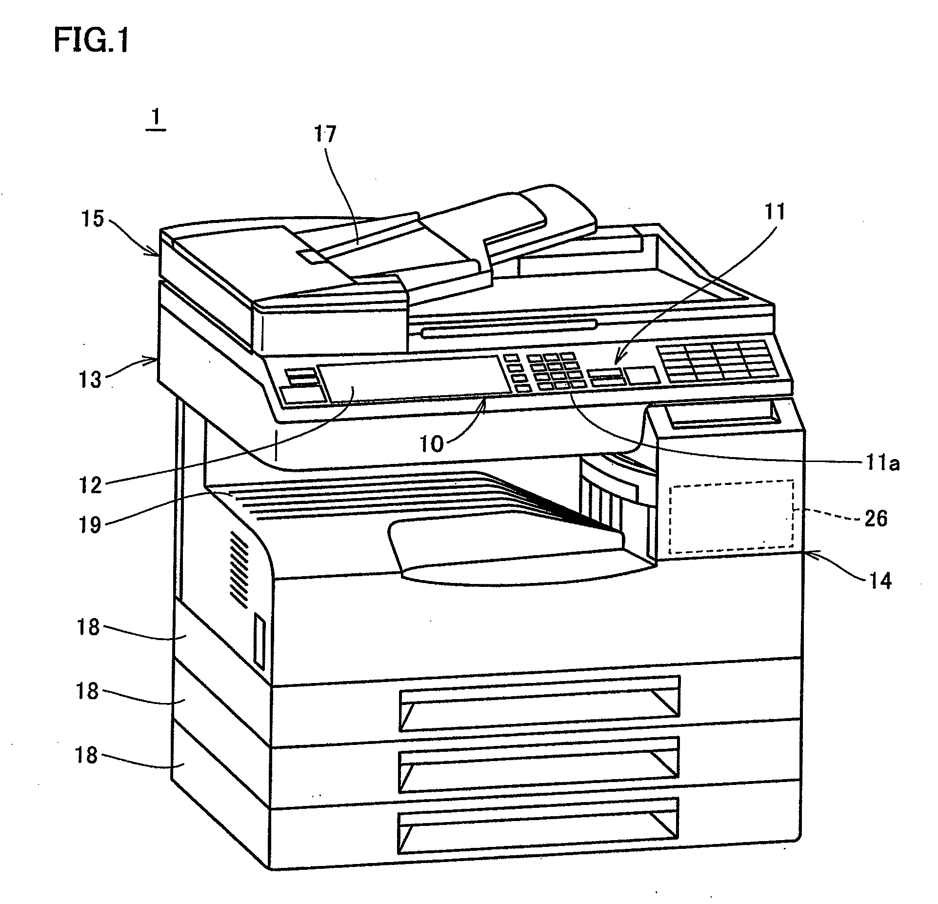
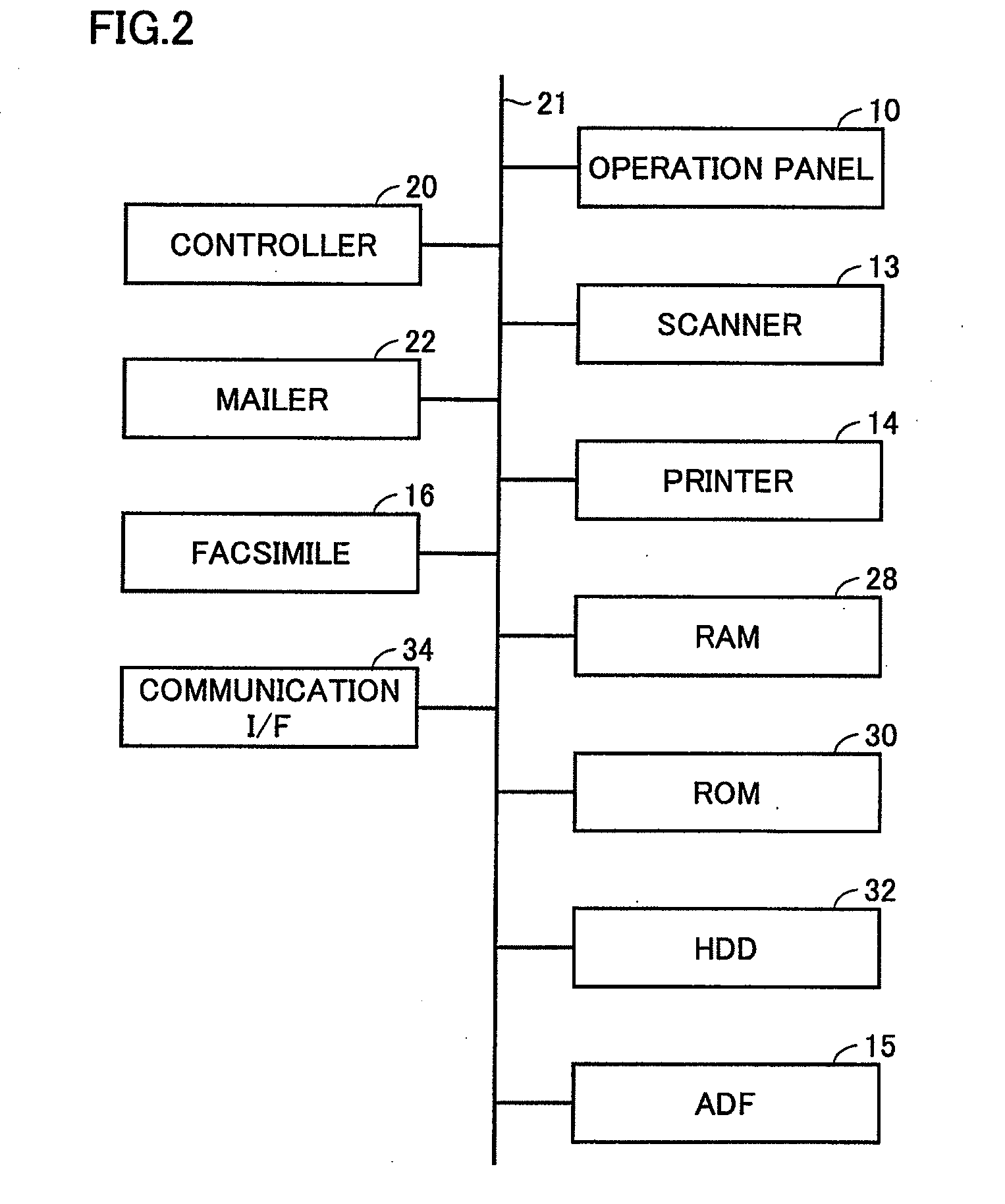
  • Image scanning device capable of obtaining at high speed a scanned image of high quality and appropriate magnification, image scanning method, image formation apparatus, and recording medium
  • Image scanning device capable of obtaining at high speed a scanned image of high quality and appropriate magnification, image scanning method, image formation apparatus, and recording medium
  • Image scanning device capable of obtaining at high speed a scanned image of high quality and appropriate magnification, image scanning method, image formation apparatus, and recording medium

Examples


modification 1

[0373

[0374]4. Correction in View of Document Thickness

[0375]A first modification of the present embodiment will be described based on correction in consideration of machinery difference variation set forth above and document thickness.

[0376]The thickness of a document was not particularly taken into consideration in the above description. However, the scanning magnification may vary due to variation in the thickness of a document.

[0377]A top side subscanning magnification of a top side scanning image according to variation in the document thickness will be described based on FIG. 19. The present example corresponds to the case where ADF one-side scanning is carried out based on a reference document (A4L) having a thickness of 128 (g / m2).

[0378]FIG. 19 represents the case where the scanning magnification becomes higher as the thickness of a document becomes greater than 128 (g / m2), whereas the scanning magnification becomes smaller as a function of thinner document when the thickness ...

second modification

[0429

[0430]The second modification according to an embodiment is directed to a scheme of further determining the absence / presence of execution of an electronic variable scale magnification process (decimation process) in the sub scanning direction of a top side scanned image according to a top side sub scanning magnification correction value in dual-side scanning in a magnification setting process.

[0431]It may be desirable to not execute an electronic variable scale magnification process (decimation process) in a subscanning direction of a top side scanned image when priority is given in the picture quality since an electronic variable scale magnification process will lead to degradation in the picture quality.

[0432]Therefore, in a case where the scanning magnification difference between a top side scanned image and a back side scanned image becomes smaller according to change in the scanning magnification caused by machinery difference variation in dual-side scanning, it may be des...


PUM


Abstract

An image scanning device includes a first scanner scanning a top side of a transported document at a first scanning position to obtain a first scanned image, a second scanner scanning the back side of the transported document at a second scanning position to obtain a second scanned image, a document feeder transporting a document at the second scanning position at a speed differing from the transportation speed at the first scanning position, and a controller controlling the image scanning device. The controller sets, as a scanning form of a document, either one-side scanning of scanning one side of a document through one transportation, or dual-side scanning of scanning both sides of a document through one transportation. The controller also obtains a set magnification. The controller determines the transportation speed by the document feeder such that, when one-side scanning is set, the scanning magnification in a first direction corresponding to the document transportation direction at the first scanned image attains the set magnification, and when dual-side scanning is set, the scanning magnification in the first direction at the second scanned image attains the set magnification.

Description

[0001]This application is based on Japanese Patent Application No. 2010-040620 filed with the Japan Patent Office on Feb. 25, 2010, the entire content of which is hereby incorporated by reference.BACKGROUND OF THE INVENTION[0002]1. Field of the Invention[0003]The present invention relates to an image scanning device having a dual-side scanning function to scan both sides of a document through one transportation such as a digital copy machine, facsimile, and scanner as well as, an image scanning method, an image formation apparatus, and a recording medium.[0004]2. Description of the Related Art[0005]An image scanning device employed as a copy machine or the like is conventionally known to carry out the so-called “skim reading”, i.e. scanning an image on a document, having the scanning position by a sensor such as a CCD (Charge Coupled Device) fixed, and delivering a document onto a platen glass, one page at a time, through an automatic document reader, and reading out the light refle...

Claims


Application Information

Patent Timeline
IPC IPC(8): H04N1/04
CPCH04N1/0402H04N1/393H04N1/203
Inventor IMAIZUMI, SHOJISUZUKI, TAKAYUKI
Owner KONICA MINOLTA INC
Learn More