
Apparatus and Method for Stabilizing Power to an Optical Multimode Receiver

a multi-mode receiver and power stabilization technology, applied in the direction of multi-mode transmission, fibre transmission, electrical apparatus, etc., can solve the problems of large fluctuations of optical receive power, bit errors in optical receivers, low noise, etc., and achieve the effect of successfully stabilizing received optical power

Active Publication Date: 2011-08-25
THE JOHN HOPKINS UNIV SCHOOL OF MEDICINE
View PDF17 Cites 2 Cited by
  • Summary
  • Abstract
  • Description
  • Claims
  • Application Information

AI Technical Summary

Benefits of technology

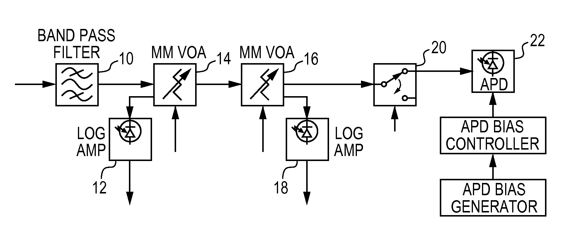
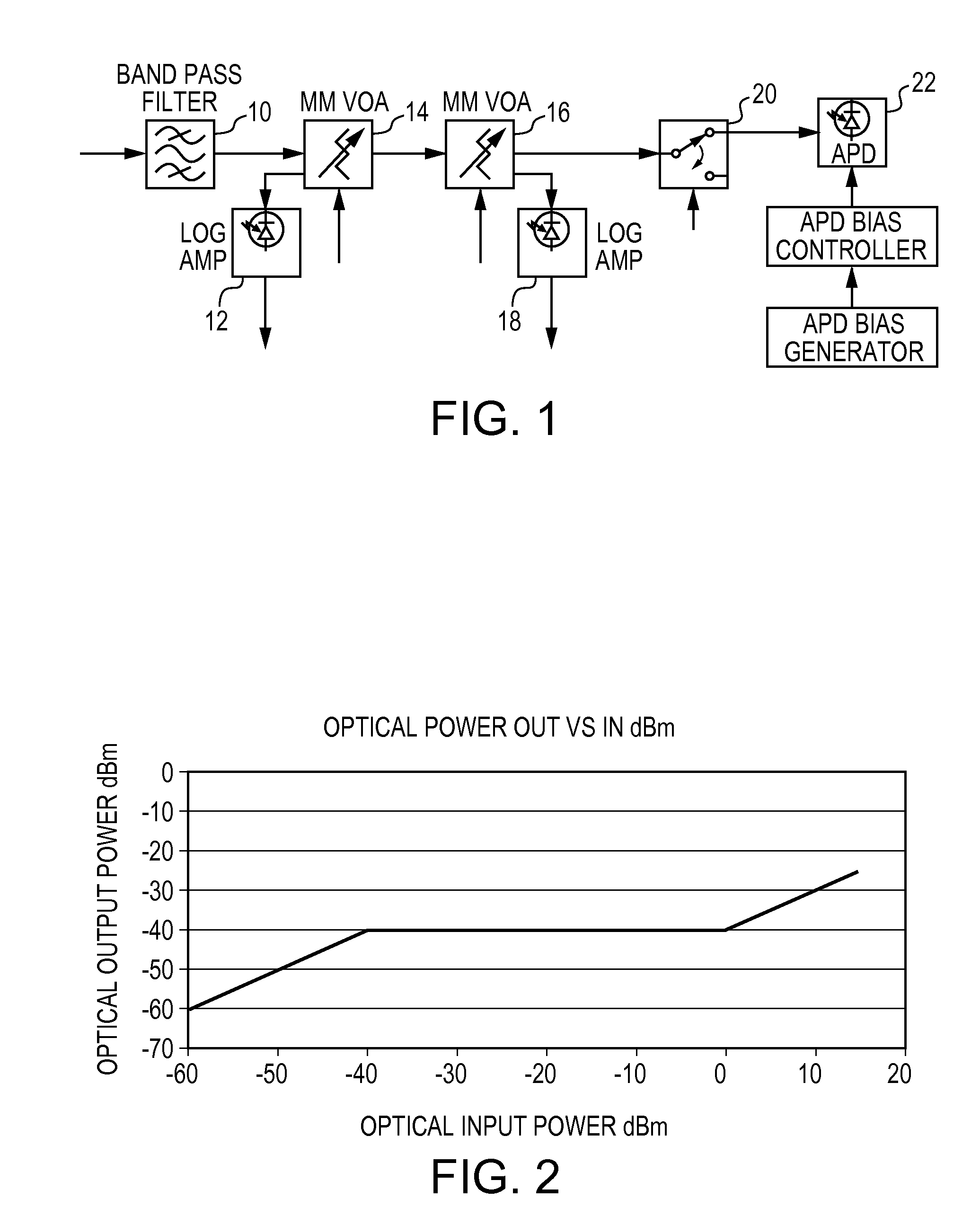
[0022]A control method which sequences the optical attenuators and an input optical switch to protect the system with frequent free space link outages;

Problems solved by technology

Free Space Optical (FSO) propagation results in large fluctuations of optical receive power.
The fluctuations can result in bit errors in optical receivers where it is desirable to stabilize the optical power and establish the best signal to noise ratio prior to detection.
In multimode systems, however, low noise, optical amplification is very difficult to achieve requiring selection of the most sensitive optical receiving device available to try to obtain the best signal to nose ratios during signal fades.
However, a risk in using these devices with systems that have rapid fluctuations in received optical power is that cases of excess optical power in combination with the high electrical bias to the APD can very easily create the avalanche current condition and destroy the detector or follow on electrical amplifiers.
If optical power is present at startup, this can result in excess power being applied to the photoreceiver.
Similarly, when the optical link goes down, the receive system will drive the attenuators to a minimal attenuation state due to lack of power.
If the link rapidly comes back online, a power spike can easily make it through the VOA, as the control system has a finite response time.
In FSO applications, all modes are often not excited which results in unexpected or unknown behavior from multimode devices.
Various technologies for implementing optical couplers exist, but not all can consistently maintain their specified coupling ratio for various mode loading conditions.
Depending on which modes are excited, the attenuation levels vary leading to unexpected system performance.
In multimode systems, amplification is not yet a readily available option, so variable optical attenuation must be used for power stabilization.
Since a control system prefers a linear function, such devices create excess demands on the signal processor.

Method used


Image

  • Apparatus and Method for Stabilizing Power to an Optical Multimode Receiver
  • Apparatus and Method for Stabilizing Power to an Optical Multimode Receiver
  • Apparatus and Method for Stabilizing Power to an Optical Multimode Receiver

Examples


Embodiment Construction

[0002]This invention was made with U.S. Government support under Department of the Air Force contract number FA8650-04-D-2413. The U.S. Government has certain rights in the invention.

BACKGROUND OF THE INVENTION

[0003]The present invention relates to an apparatus and method for optical multimode receiver power stabilization and protection particularly in free space optical systems.

[0004]Free Space Optical (FSO) propagation results in large fluctuations of optical receive power. The fluctuations can result in bit errors in optical receivers where it is desirable to stabilize the optical power and establish the best signal to noise ratio prior to detection.

[0005]In single mode systems optical power stabilization can be accomplished with active low noise optical amplification with an optical gain that can be rapidly adjusted to negate the optical power fluctuations prior to detection using a PIN photodiode. In multimode systems, however, low noise, optical amplification is very difficult...


PUM


Abstract

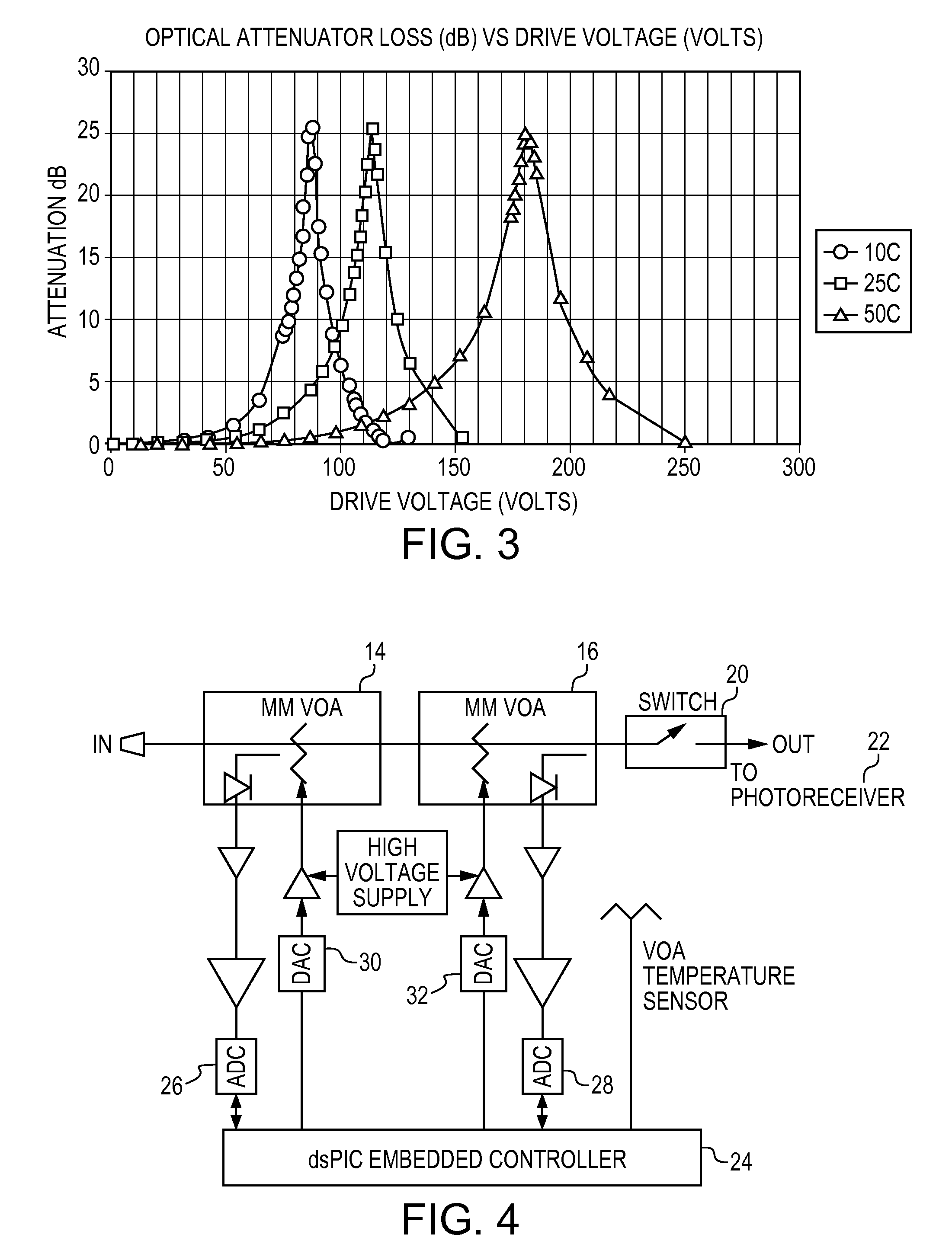
To stabilize power to an optical multimode receiver a multimode variable optical attenuator is connected to the receiver with the attenuator's voltage being controlled using a feedback signal provided by an output detector, the signal being processed using a control algorithm based on proportional-integrate-differential theory.

Description

CROSS-REFERENCE TO RELATED APPLICATIONS[0001]This application relates to U.S. provisional application No. 61 / 305,356, filed on Feb. 17, 2010, which is incorporated herein by reference in its entirety.STATEMENT OF GOVERNMENTAL INTEREST[0002]This invention was made with U.S. Government support under Department of the Air Force contract number FA8650-04-D-2413. The U.S. Government has certain rights in the invention.BACKGROUND OF THE INVENTION[0003]The present invention relates to an apparatus and method for optical multimode receiver power stabilization and protection particularly in free space optical systems.[0004]Free Space Optical (FSO) propagation results in large fluctuations of optical receive power. The fluctuations can result in bit errors in optical receivers where it is desirable to stabilize the optical power and establish the best signal to noise ratio prior to detection.[0005]In single mode systems optical power stabilization can be accomplished with active low noise opt...

Claims


Application Information

Patent Timeline
Patent Type & Authority Applications(United States)
IPC IPC(8): H04B10/06
CPCH04B10/674H04B10/2581
Inventor SLUZ, JOSEPH E.JUAREZ, JUAN C.YOUNG, DAVID W.
Owner THE JOHN HOPKINS UNIV SCHOOL OF MEDICINE
Learn More