Lock hopper

a technology of lock hopper and hopper body, which is applied in the direction of conveyors, separation processes, containers, etc., can solve the problems of increased maintenance costs of exhaust gas treatment equipment and exhaust gas treatment equipment, decrease in the average particle diameter, and inoperable lock hopper systems, etc., and achieves the effect of large transfer amoun

Active Publication Date: 2011-08-25
J POWER ENTECH
View PDF27 Cites 49 Cited by
  • Summary
  • Abstract
  • Description
  • Claims
  • Application Information

AI Technical Summary

Benefits of technology

[0076]In the lock hopper of the present invention, when a granular substance is discharged from the hopper, a gas (e.g. nitrogen) is introduced into the hopper; therefore, there is no introduction of a gas of lower system into the hopper. Also, when a granular substance is introduced into the hopper, the gas in the hopper flows toward an upper system in place of the granular substance being introduced and there is no introduction of a gas of upper system into the hopper. Accordingly, there is no gas flow from one system to the other system. Also, there is no gas release outside from the system.
[0077]Also, in the lock hopper of the present invention, since each hopper comprises a gas-introducing pipe, a gas (e.g. n

Problems solved by technology

Further, when the dry type, exhaust gas treatment apparatus is operated for many hours, the adsorbent undergoes abrasion and is broken depending upon the operation hour, resulting in a decrease in average particle diameter.
As a result, a relation

Method used


Image

  • Lock hopper
  • Lock hopper
  • Lock hopper

Examples


first embodiment

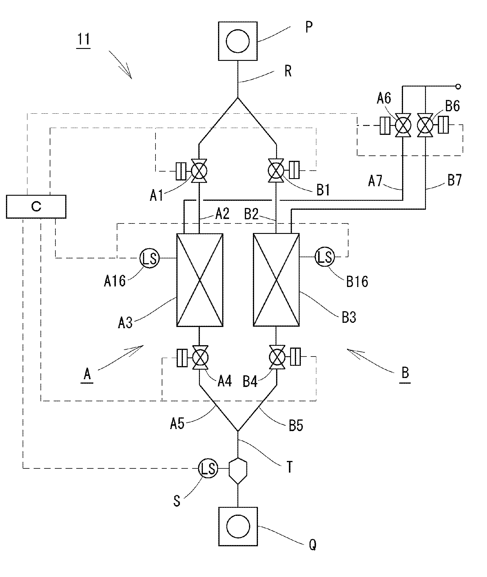
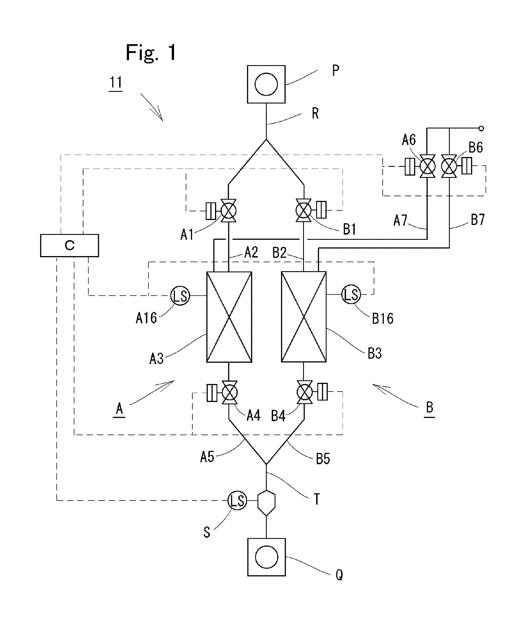
[0114]Description is made below on the embodiment of the present invention. FIG. 1 is an assembly drawing of the present invention.

[0115]A lock hopper 11 is constituted by a lock hopper A and a lock hopper B both arranged side by side. The lock hopper 11 alternates the receiving and discharging of a granular substance repeatedly, using two lock hoppers A and B. Further, metering feeders P, Q, etc. are provided between the lock hopper 11 and an upper system or a lower system, whereby the granular substance can be continuously transferred downward. In this lock hopper 11, the two lock hoppers A and B are used alternately, whereby the free movement of a gas between the upper system and the lower system is prevented.

[0116]In the lock hopper A, one end of a granular substance entrance piper A2 is connected to the top of a hopper A3 formed air-tightly. An entrance valve A1 is interposed in the granular substance entrance pipe A2.

[0117]One end of a granular substance exit pipe AS is connec...

second embodiment

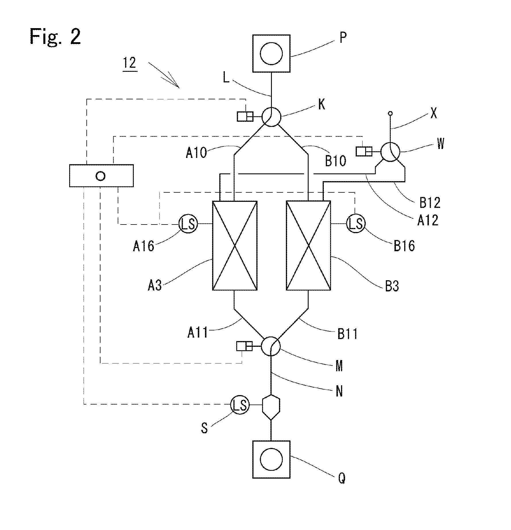
[0132]Next, the present invention is described with reference to the assembly drawing shown in FIG. 2.

[0133]In FIG. 2, a lock hopper 12 corresponds to a constitution obtained by, in the lock hopper 11 of FIG. 1, replacing the entrance valve A1 and the entrance valve B1 with an entrance passage-switching valve K, replacing the exit valve A4 and the exit valve B4 with an exit passage-switching valve M, and replacing the gas-introducing valve A6 and the gas-introducing valve B6 with a gas passage-switching valve W.

[0134]The lock hopper 12 has a hopper A3 and a hopper B3 both formed air-tightly and arranged side by side. An entrance passage-switching valve K is provided above the lock hopper 12 and an exit passage-switching valve M is provided below the lock hopper 12. The entrance of the entrance passage-switching valve K is connected to a granular substance-introducing pipe L. One exit of the entrance passage-switching valve K is connected to the top of the hopper A3 by an upper branc...


PUM


Abstract

The present invention relates to
A lock hopper (11) provided with air-tight hoppers (A3, B3) arranged side by side with entrance valves (A1, B1) arranged above the air-tight hoppers (A3, B3) and exit valves (A4, B4) arranged below the air-tight hoppers (A3, B3).
The lock hopper (11) performs control which alternately repeats the following states: a state in which granular substances in an upper system are placed in one of the hoppers and gas is supplied into the other hopper to discharge granular substances from the inside of the other hopper to a lower system and a state in which the granular substances in the upper system are placed in the other hopper and gas is supplied to said hopper to discharge granular substances from the inside of said hopper to the lower system.
Also provided is a method of transferring granular substances in an upper system to a lower system by using above-described lock hopper, wherein gas having a volume corresponding to the volume of at least the granular substances to be discharged to the lower system is supplied to a hopper in a state in which the granular substances are being discharged from the hopper to the lower system.

Description

TECHNICAL FIELD[0001]The present invention relates to a lock hopper which is provided between an upper system and a lower system when a granular substance is allowed to flow down to transfer from the upper system to the lower system. This lock hopper can transfer a granular substance continuously. Moreover, the lock hopper can block the gas flow between the upper system and the lower system and promises a large transfer amount.BACKGROUND ART[0002]Lock hopper has an entrance valve above the hopper formed air-tightly and an exit valve below the hopper formed air-tightly. In lock hopper, the entrance valve and the exit valve are opened or closed alternately so that both the entrance valve and the exit valve are not in an “open” state simultaneously. As a result, with lock hopper, a granular substance can be transferred from an upper system to a lower system in a state that the flow of gas is blocked between the upper system and the lower system. Here, the upper system and the lower sys...

Claims


Application Information

Patent Timeline
IPC IPC(8): B65G53/56B65G65/40B65D90/54
CPCB01J2208/00752B65G53/12B65G53/40C10J2200/156B01D53/12C10J2300/093
Inventor FURUYAMA, KUNINORIMIYA, MASAHIROSUZUKI, RYO
Owner J POWER ENTECH
Why Eureka
Try Eureka