Fuel cells and other products containing modified carbon products

a technology of carbon products and fuel cells, which is applied in the direction of cell components, metal/metal-oxide/metal-hydroxide catalysts, physical/chemical process catalysts, etc., can solve the problems of difficult creation of three-dimensional reaction zones on electrodes in contact with electrolyte, and achieve the reduction of catalyst efficiency, poor catalyst utilization, and electrode performance.

Inactive Publication Date: 2003-01-23
CABOT CORP
View PDF19 Cites 91 Cited by
  • Summary
  • Abstract
  • Description
  • Claims
  • Application Information

AI Technical Summary

Benefits of technology

0062] Catalyst utilization has been rather poor in conventional fuel cells because of the nature of the interface. It was found that, in conventional electrodes, a large part of the catalyst is not effective. The electrochemical reaction takes place only in those areas where catalyst is accessible both to the reactant gas and the electrolyte. PTFE makes the catalytic layer partly impermeable to the electrolyte so that the catalyst efficiency is lowered, also resulting in the decrease of the electrode performance. On the other hand, a large amount of PTFE is required in the gas diffusion layer to prevent the electrolyte diffusivity over a long period of time. This results in the reduction of the gas mass transport efficiency due to the blocking effect of PTFE inside the fine porous structure.
0063] Since the modified carbon products of the present invention promote hydrophobic and / or hydrophilic properties on a molecular scale, there is no random wetting of the carbon products and a very even distribution of the wetting characteristics exists throughout the active layer for instance. Thus, the unwanted excessive wetting of the carbon products can be avoided throughout the entire active layer which then leads to a long term operation thus promoting the extension of the service life of the electrode. Further, with respect to the blocking layer, with a modified carbon product having attached hydrophobic organic groups, the blocking layer quite effectively blocks any electrolyte and permits the greatest amount of air diffusion.
0064] The fuel cells and the components of the fuel cell, including the electrodes described in U.S. Pat. Nos. 5,783,325; 5,521,020; 5,733,430; 5,561,000; and 5,116,592 can be used in the present invention and these patents are incorporated in their entirety by reference herein. These patents provide examples of catalyst particles, fluoropolymers, various layers of electrodes and the like which can be used herein or can be further modified as described here with the modified carbon product or the modified carbon product associated with the catalyst.
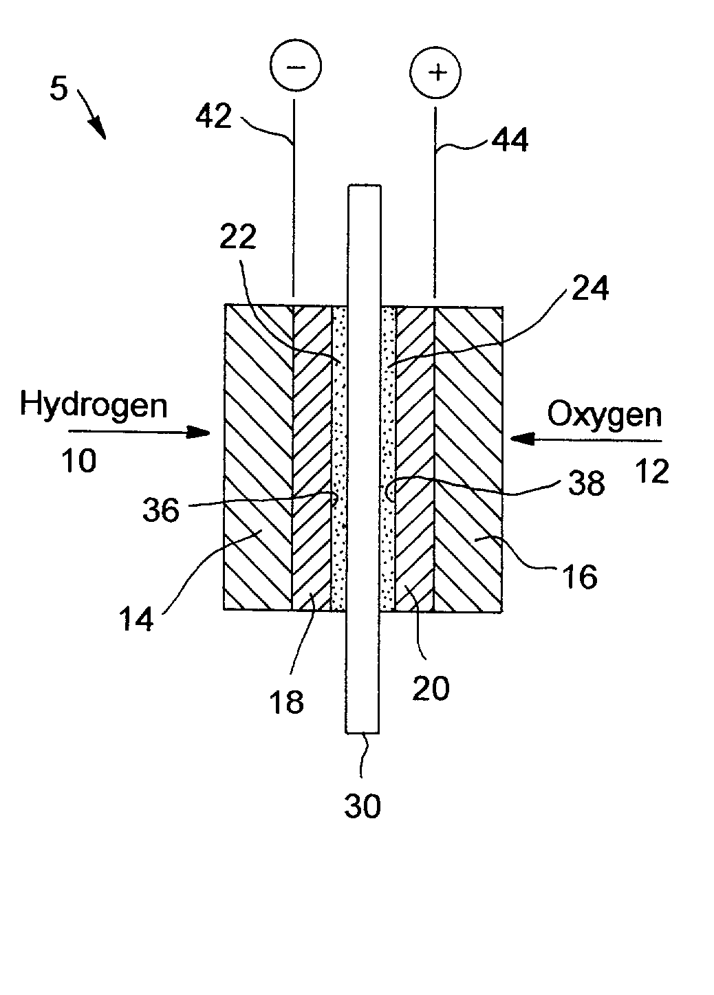
0065] FIG. 4 provides one example of a fuel cell 5 wherein electrodes 18 and 20 are shown, and wherein 36 and 38 depict catalyst layers. Anode connection 42 and cathode connection 44 are shown and are connected to an external circuit (not shown). 22 and 24 reflect optional electrolyte deposits that are in contact with the solid membrane 30. The fuel cell includes gaseous reactants, such as a fuel source 10 and an oxidizer source 12, wherein the gases 10 and 12 diffuse through anode backing layer 14 and cathode baking layer 16, respectively, to porous electrodes forming an oxidizing electrode or anode 18 and a reducing electrode or cathode 20. Further details of this conventional fuel cell are set forth in U.S. Pat. No. 5,521,020 and the other patents referenced above.
0066] Further to the above embodiments and as an additional embodiment that can be used separately with various fuel cells and other devices that use catalysts, the present invention further involves methods to deposit catalyst on substrates or support such as carbon black supports. In the methods, a catalyst containing composition, such as a metal catalyst like platinum, is reacted with a modified carbon product, wherein the modified carbon product preferably has an attached organic group which is ionic and preferably anionic. The catalyst is preferably a metal catalyst which is in the form of an ionic metal catalyst precursor (e.g., a cationic metal catalyst containing composition), such as those described below. In the reaction, a modified carbon product is formed having attached an ionic group associated with a counterionic catalyst group. Examples of such groups are shown below as well. This modified carbon product that contains the ionic group associated with the counterionic catalyst group is then subjected to a reducing process by using a reducing agent to reduce the counterionic catalyst group to a metal catalyst in order to deposit the metal catalyst on the modified carbon product. Examples of reducing agents preferably include gases or liquids, such as hydrogen gas with or without an inert gas. Other reducing agents described previously can be used. The reduction can occur at any temperature, for instance from about 80.degree. C. or higher. If contaminants are present such as NH.sub.4.sup.+ or Cl.sup.-, these contaminants can be removed by passage of the reaction product through a mixed bed of ion exchange resins in H.sup.+ and OH.sup.- forms. As shown in Example 2, this process leads to an excellent distribution of the metal catalyst throughout the carbon and this dispersion can then be used to form, using standard techniques, (e.g., mixing the modified carbon product with catalyst with a binder and forming a layer) a carbon support containing the catalyst. Furthermore, extremely small catalyst particle sizes can be formed, e.g., 2 nm or lower or 1 nm or lower which is excellent for fuel cells especially when created on a proton conducting surface.
0067] Catalysts used for the oxygen reduction reaction in fuel cells and gas diffusion electrodes typically contain platinum particles deposited on carbon black supports. Preferably, the maximum catalyst activity is achieved when the Pt particles have mean sizes of from about 2 to about 3 nm and are uniformly distributed on the support material. To achieve this distribution, various methods can be used. For instance, the reduction of H.sub.2PtCl.sub.6 in the presence of carbon black can be used. The use of H.sub.2PtCl.sub.6 to deposit Pt on carbon blacks with attached organic groups, such as --C.sub.6H.sub.4SO.sub.3H groups, can result in the deposition of Pt particles that are substantially larger than 2 to 3 nm. Moreover, Pt agglomeration can occur, which may indicate less than desirable Pt distribution on the support material. Another method to deposit the Pt particles is to use an ion exchange procedure to deposit the Pt on the carbon products having an attached organic group.

Problems solved by technology

A three dimensional reaction zone on an electrode in contact with the electrolyte is not created easily since the PEM electrolyte is a solid.

Method used


Image

  • Fuel cells and other products containing modified carbon products
  • Fuel cells and other products containing modified carbon products
  • Fuel cells and other products containing modified carbon products

Examples


example 1

[0093] Five membrane electrode assemblies (MEA's) were constructed. The reagents used were Pt black and 20 weight % Pt on VULCAN XC 72 carbon black (both from Alfa Aesar), Teflon PTFE 30 dispersion (DuPont) containing 60 weight % PTFE, hydrophobic Toray paper (Toray), Nafion 117 membrane (DuPont), Nafion solution, 5 weight % (Electrochem, Inc.) and Kynar 721 polyvinylidene fluoride powder (AtoFina). All MEA's were fabricated with a Nafion 117 membrane and an anode that consisted of 4.0 mg Pt black / cm.sup.2. Four MEA's were constructed using a standard procedure wherein the supported catalyst was bonded with PTFE. In these cases, a dispersion consisting of 90 parts of the supported Pt catalyst and 10 parts PTFE was mixed by sonification, flocculated by acidification to pH 3, and dried at 105.degree. C. The powder was then deposited on the 2 hydrophobic Toray paper to form a catalyst layer containing 0.5 mg Pt / cm.sup.2. The catalyst layer was heated at 360.degree. C. for 30 minutes to...

example 2

[0138] BLACK PEARLS 2000 carbon black, 50 g, was diazotized with sulfanilic acid (about 25 g), resulting in the attachment of a high level of --C.sub.6H.sub.4SO.sub.3Na groups. The resulting dispersion was diafiltered to remove the reaction byproducts and then passed through a cation exchange column, in its hydrogen form, to replace the Na.sup.+ in the attached group with H.sup.+ (i.e., forming --C.sub.6H.sub.4SO.sub.3H groups). A solid product was obtained after drying the dispersion at 75.degree. C. To an aqueous dispersion of the treated black (2 to 5 g), a solution of either [Pt(NH.sub.3).sub.4](OH).sub.2 or [Pt(NH.sub.3).sub.4]Cl.sub.2 was added to achieve Pt loadings of either about 1 mmoles / g treated black or 0.65 mmoles / g treated black, respectively. The resulting products were dried at 75.degree. C. Samples were then placed in a tube furnace, heated to a specified temperature (105, 120, and 140.degree. C.) under N.sub.2 and then reduced in a stream of a mixture of H.sub.2 a...

example 3

[0148] CSX 619 carbon black, having a BET surface area of about 600 m.sup.2 / g, a t-area of about 400 m.sup.2 / g and a DBP of 100 cc / 100 g, was diazotized with sulfanilic acid. The resulting product, after diafiltration, ion exchange and drying, contained 0.9 mmoles / g of attached --C.sub.6H.sub.4SO.sub.3H groups. This treated carbon black was then dispersed in LLDPE in a 60 cc Brabender mixer to achieve a treated black loading of 40 weight %. Samples of the resulting product were than compressed at a pressure of 30,000 lb at a temperature of 150.degree. C. to form membranes having a thickness of about 60 microns. A sample of the neat LLDPE was also compressed to form a membrane of comparable thickness (63 microns).

[0149] The treated black loaded LLDPE membrane was sandwiched between two hydrated Nafion 112 membranes and then bonded together by hot pressing at 140.degree. C. at 5000 psi for about 2 minutes. The thickness of the membrane sandwich was measured to be 124 microns. A compos...


PUM

PropertyMeasurementUnit
thicknessaaaaaaaaaa
particle sizeaaaaaaaaaa
thickaaaaaaaaaa

Abstract

Fuel cells are described and contain a gas diffusion electrode, a gas diffusion counter-electrode, an electrolyte membrane located between the electrode and counter-electrode. The electrode or counter-electrode or both contain at least one modified carbon product. The electrolyte membrane can also or alternatively contain modified carbon products as well. The modified carbon product is a carbon product having attached at least one organic group. Preferably the organic group is a proton conducting group and/or an electron conducting group. The present invention preferably permits the elimination of fluoropolymer binder in the active or catalyst layer and further preferably leads to a thinner active layer and/or a thinner electrolyte membrane. Other uses and advantages are also described.

Description

[0001] This application claims the benefit under 35 U.S.C. .sctn.119(e) of prior U.S. Provisional Patent Application No. 60 / 282,944 filed Apr. 11, 2001, U.S. Provisional Patent Application No. 60 / 307,890 filed Jul. 26, 2001, and U.S. Provisional Patent Application No. 60 / 363,307 filed Mar. 8, 2002, and is also a continuation-in-part of U.S. patent application Ser. No. 09 / 833,202 filed Apr. 11, 2001, which are all incorporated in their entirety by reference herein.[0002] The present invention relates to fuel cells and gas diffusion electrodes which can be used in a variety of applications. The present invention further relates to methods of preparing the fuel cells and other products. The present invention further relates to materials particularly suitable in the manufacture of fuel cells and gas diffusion electrodes and other electrodes.[0003] A gas diffusion electrode (GDE) typically contains a hydrophobic polymer in contact with a high surface area electrically conductive or semic...

Claims


Application Information

Patent Timeline
Patent Type & Authority Applications(United States)
IPC IPC(8): H01M4/88H01M4/92H01M4/96H01M8/02C25B13/08H01M8/10
CPCH01M4/96H01M8/1004Y02E60/523Y02E60/50
Inventor MENASHI, JAMEEL
Owner CABOT CORP
Why Eureka
Try Eureka