Method for manufacturing ink jet cartridge

a manufacturing method and ink jet technology, applied in metal-working equipment, printing, metal-working equipment, etc., can solve the problems of deterioration of material efficiency, increased costs even more than previously, and difficulty in cleaning the urethane sponge used for the negative-pressure generating member, etc., to reduce the leakage of ink from the ink cartridge, reduce the waste of ink absorber materials, and simple and stably forming

Inactive Publication Date: 2011-09-01
CANON KK
View PDF31 Cites 17 Cited by
  • Summary
  • Abstract
  • Description
  • Claims
  • Application Information

AI Technical Summary

Benefits of technology

[0019]The invention has been made in view of the above problems. Specifically, the object of the invention is to provide a method for manufacturing an ink jet cartridge capable of simply and stably forming dense or coarse distribution in an ink absorber with no waste of an ink absorber material. Another object of the invention is to provide a method for manufacturing an ink jet cartridge capable of reducing leakage of ink from an ink cartridge.
[0021]According to the invention, it is possible to manufacture an ink jet cartridge through simple steps without generating waste material and having excellent efficiency in the use of ink, and to provide a manufacturing method of a cheap ink jet cartridge which is inexpensive and low in running cost. Additionally, it is also possible to provide a manufacturing method of an ink jet cartridge with reduced ink leakage.

Problems solved by technology

However, it is difficult to clean the urethane sponge used for the negative-pressure generating member of the ink tank or the fiber assembly in which intersections between the fibers are bonded together, in every detail in order to be reused as a product again.
Accordingly, if an ink absorber is made in accordance with an ink jet cartridge of a complicated shape, the efficiency in the use of a material will deteriorate and costs will increase even more than previously.
As a result, ink charging efficiency will deteriorate, the frequency of ink jet cartridge replacement will increase, and the printing cost (running cost) for printing per page will increase.
If it is not possible to efficiently supply the ink which is maintained at a negative pressure in the ink absorber to the ink discharge device, it is impossible to use the ink with a large amount of ink remaining in the ink absorber, which will lead to an increase in the running cost.
Additionally, when an ink absorber mass of material is cut into a complicated shape, a surplus portion incapable of being used as an ink absorber will be generated in the mass of material.
That is, the complicated cut-out step will increase the waste of material, and thus costs will increase.
However, in this case, there is a concern that the steps are complicated and that dense or coarse distribution is upset due to the handling when the fibers are inserted after being cut because the fibers are not fused together.

Method used


Image

  • Method for manufacturing ink jet cartridge
  • Method for manufacturing ink jet cartridge
  • Method for manufacturing ink jet cartridge

Examples


first embodiment

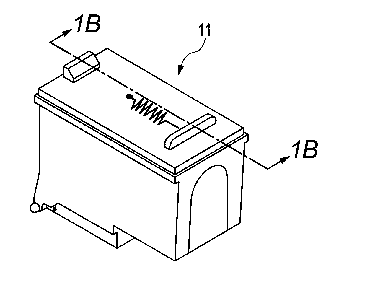
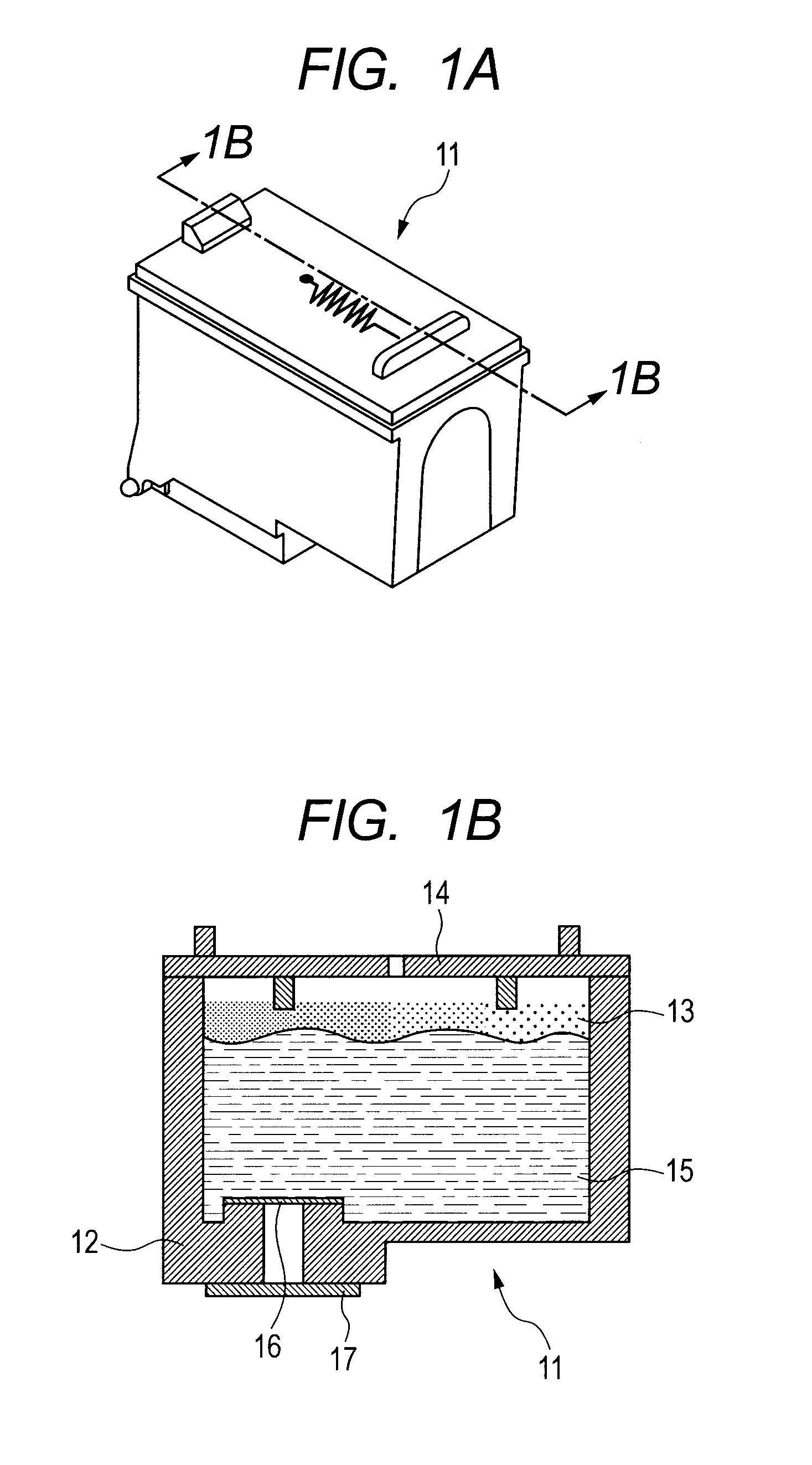
[0040]FIGS. 1A and 1B are a schematic view and a sectional view illustrating a first embodiment of an ink jet cartridge 11 manufactured by a manufacturing method of the invention. FIG. 1B is a sectional view taken along the line 1B-1B of FIG. 1A. The ink jet cartridge 11 includes an ink storage portion having a tank case 12 which stores ink, and a lid 14, and an ink discharge device 17. An ink absorber 13 which holds ink is housed in the tank case (container) of the ink storage portion, and the ink 15 filled into the ink absorber is supplied to the ink discharge device 17 fixed to the bottom of the tank case 12 via an ink supply portion 16. The ink discharge device 17 adopts a so-called ink jet type which has elements which generate heat energy, vibration energy, or the like which is available for droplet discharge. Additionally, the tank case 12 has a rectangular parallelepiped shape, and the ink supply portion 16 is disposed near a longitudinal end of a bottom face of the tank cas...

second embodiment

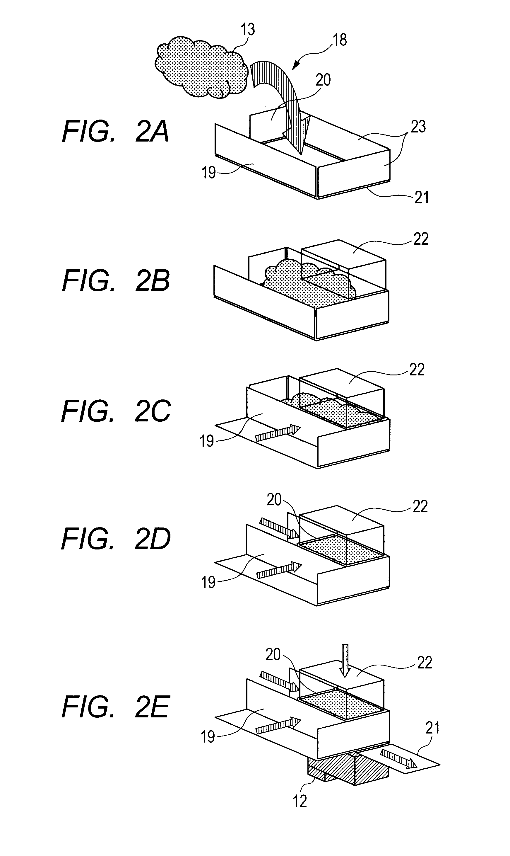
[0047]Schematic views of a second embodiment in the manufacturing method of the invention are illustrated in FIGS. 6A and 6B. Similarly to the first embodiment, the ink absorber 13, which is a fiber assembly in which intersections between fibers are not fused together, is charged into the compression and insertion apparatus 18, and the ink absorber 13 is pushed toward the fixing plate 23 in the order of the side plate 19 and the side plate 20. Since the internal volume of the compression and insertion apparatus 18 into which the ink absorber 13 is charged is enlarged in advance, the density distribution is rarely formed simply by moving the all the fibers in the direction of the side plate 20 when the ink absorber has been pushed by the side plate 19. Since the escape space of all the fibers decreases when the ink absorber is further pushed by the side plate 20, the ink absorber is slightly compressed, and the density distribution is slightly formed. Next, the bottom plate 21 is mov...

third embodiment

[0049]The third embodiment is a manufacturing method in a case where it is intended to make the capillary force of the part of the ink absorber located near the ink supply portion 16 higher. Schematic views of a third embodiment in the manufacturing method of the invention are illustrated in FIGS. 9A to 9D. Similarly to the first embodiment, first, a predetermined amount of the ink absorber 13, which is a fiber assembly in which intersections between fibers are not fused together, is charged into the compression and insertion apparatus 18. Next, as illustrated in FIGS. 9B and 9C, the insertion block 22 is moved to the upper surface portion of the absorber 13, and one face of the ink absorber 13 is pushed by the side plate 19. In the present embodiment, the following method is used during such operation. That is, as illustrated on the right of FIG. 9A, a convex portion 26 is provided in advance at a portion of the bottom plate 21. In other words, as illustrated on the right of FIG. 9...


PUM

PropertyMeasurementUnit
lengthaaaaaaaaaa
lengthaaaaaaaaaa
capillary forceaaaaaaaaaa

Abstract

A predetermined amount of an ink absorber, which is a fiber assembly in which intersections between fibers are not fused together, is charged into a compression and insertion apparatus. A rectangular parallelepiped-shaped insertion block is moved to an upper surface portion of the absorber, and one face of the ink absorber is pushed by a side plate. As such, a part excluding the part of the ink absorber which faces the side plate is compressed and surrounded. In this state, the ink absorber is compressed by the side plate. The ink absorber is inserted into a tank case by making a bottom plate slide, thereby opening the bottom face of the ink absorber and by moving down the insertion block.

Description

BACKGROUND OF THE INVENTION[0001]1. Field of the Invention[0002]The present invention relates to a method for manufacturing an ink jet cartridge used for an ink jet recording apparatus, and a method for manufacturing the ink jet cartridge in which an ink discharge device which discharges ink, and an ink storage portionink storage portion which stores ink to be supplied to the ink discharge device are integral with each other. Particularly, the present invention relates to a method for manufacturing an ink jet cartridge having a step of compressing and inserting an absorber including fibers to be arranged within an ink storage portion.[0003]2. Description of the Related Art[0004]Conventionally, it is usual that an ink jet cartridge used for an ink jet recording apparatus is designed such that the pressure within a tank case becomes a negative pressure with respect to an atmospheric pressure in order to maintain the ink supply performance to an ink jet recording head.[0005]As a means ...

Claims


Application Information

Patent Timeline
Patent Type & Authority Applications(United States)
IPC IPC(8): B23P17/00
CPCB41J2/17513Y10T29/49908B41J2/17559
Inventor YAMAMOTO, HIROYUKIHINAMI, JUNSHIBATA, TAKESHIMIYAZAKI, HIROTAKAKURIHARA, YOSHIAKISHIMAMURA, RYOTAKAHASHI, TOMOHIROTSUKAMOTO, NAOYAFUJII, TATSUNORIISHIKAWA, MASASHI
Owner CANON KK
Why Eureka
Try Eureka