Vehicle drive shaft and vehicle equipped with vehicle drive shaft

a technology of vehicle drive shaft and drive shaft, which is applied in the direction of fluid couplings, gearing, couplings, etc., can solve the problems of difficult to accurately set a predetermined angle, increase vibration or noise of the drive train, and cause etc., to achieve accurate and easy machined, suppress the occurrence of torsional resonance of the drive train, and ensure durability and control the effect of stability

Inactive Publication Date: 2011-09-01
TOYOTA JIDOSHA KK
View PDF6 Cites 22 Cited by
  • Summary
  • Abstract
  • Description
  • Claims
  • Application Information

AI Technical Summary

Benefits of technology

[0009]The invention provides a vehicle drive shaft that allows its components to be accurately and easily machined and that, in addition, is able to suppress occurrence of drive train torsional resonance while ensuring durability and stability of control, and also provides a vehicle equipped with the vehicle drive shaft.

Problems solved by technology

Incidentally, in a drive train including the vehicle drive shafts according to the related art, there is a problem that drive train torsional resonance occurs to increase vibrations or noise, such as muffled noise in a vehicle cabin.
Incidentally, in the vehicle drive shaft having the intermediate shaft 100, there has been a problem that it is difficult to accurately set a predetermined angle θ1 that determines the variable characteristic of torsional rigidity of the intermediate shaft 100.

Method used


Image

  • Vehicle drive shaft and vehicle equipped with vehicle drive shaft
  • Vehicle drive shaft and vehicle equipped with vehicle drive shaft
  • Vehicle drive shaft and vehicle equipped with vehicle drive shaft

Examples


Embodiment Construction

[0038]Hereinafter, an embodiment of the invention will be described with reference to the accompanying drawings. Note that the drawings in the following embodiment are appropriately simplified or modified and do not always accurately illustrate the scale ratio, shape, and the like, of portions.

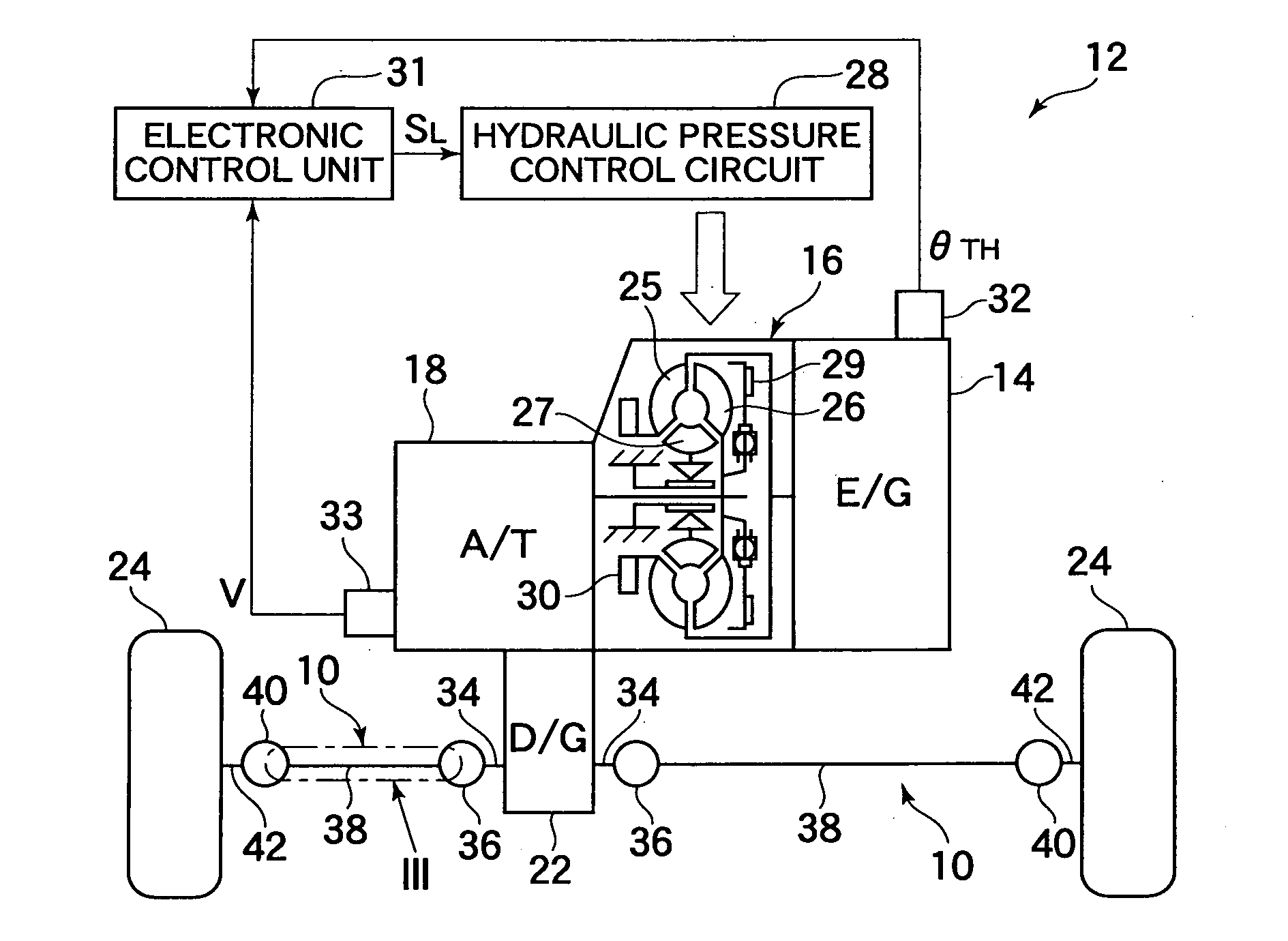
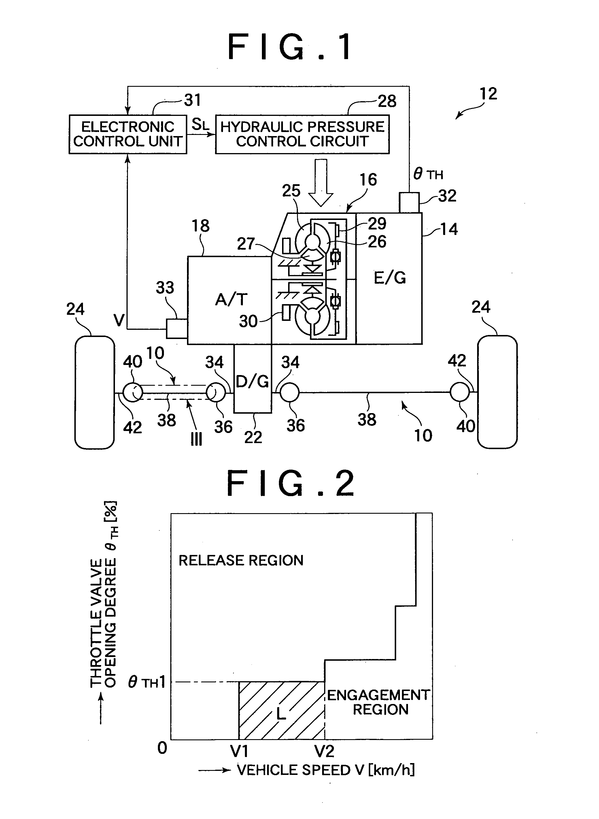
[0039]FIG. 1 is a view that shows the schematic configuration of a vehicle drive device 12 equipped with vehicle drive shafts (vehicle power transmission members) 10 according to an embodiment of the invention and a relevant portion of a control system provided for the vehicle. As shown in FIG. 1, the drive device 12 is used for a front-engine front-drive (FF) vehicle, and includes an engine 14 as a power source for propelling the vehicle. The engine 14 is, for example, formed of an internal combustion engine, such as a gasoline engine and a diesel engine. Power output from the engine 14 is transmitted to a differential gear unit 22 via a well-known torque converter 16 and automatic transmissi...


PUM


Abstract

A vehicle drive shaft includes: a first shaft portion, having a core shaft portion and a sleeve shaft portion coaxially arranged at one end, and a second shaft portion, having a spline hole portion and a second engagement protrusion at one end. A spline shaft portion and a first engagement protrusion are provided at distal ends of the core shaft portion and sleeve shaft portion. The spline hole portion is nonrotatably fixed to the spline shaft portion. The second engagement portion contacts the first engagement portion when a relative torsion allowable angle therebetween is larger than or equal to a gap. When the relative torsion allowable angle is smaller than the gap, torque is transmitted via the core shaft portion. When the relative torsion allowable angle is larger than or equal to the gap, torque is transmitted via not only the core shaft portion but also the sleeve shaft portion.

Description

BACKGROUND OF THE INVENTION[0001]1. Field of the Invention[0002]The invention relates to a vehicle drive shaft, which serves as a power transmission member, provided in a power transmission path of a vehicle and a vehicle equipped with the vehicle drive shaft.[0003]2. Description of the Related Art[0004]Vehicle drive shafts are known as rotary shafts provided in a power transmission path from a power source for propelling a vehicle to drive wheels in order to transmit power output from the power source to the drive wheels. For example, drive shafts described in Japanese Patent Application Publication No. 2004-9843 (JP-A-2004-9843) correspond to the above vehicle drive shafts. The drive shafts described in JP-A-2004-9843 are front wheel drive shafts provided between a front wheel differential gear unit and front wheels in a front-engine front-drive (FF) vehicle, and are used to transmit torque from the front wheel differential gear unit to the front wheels. Other than the above, the ...

Claims


Application Information

Patent Timeline
Patent Type & Authority Applications(United States)
IPC IPC(8): F16H45/02F16C3/02
CPCF16D1/101F16D2001/103F16D3/185F16D3/10
Inventor YAMAMOTO, TAKEOYAMANO, SHOGOKOBATA, KEISHI
Owner TOYOTA JIDOSHA KK
Why Eureka
Try Eureka