
Expansion tank

a technology of expansion chamber and expansion chamber, which is applied in the direction of machines/engines, transportation and packaging, containers, etc., can solve the problem of not being able to mix coolants, and achieve the effect of reducing the pressure within the expansion chamber

Inactive Publication Date: 2011-09-01
SCANIA CV AB
View PDF4 Cites 17 Cited by
  • Summary
  • Abstract
  • Description
  • Claims
  • Application Information

AI Technical Summary

Benefits of technology

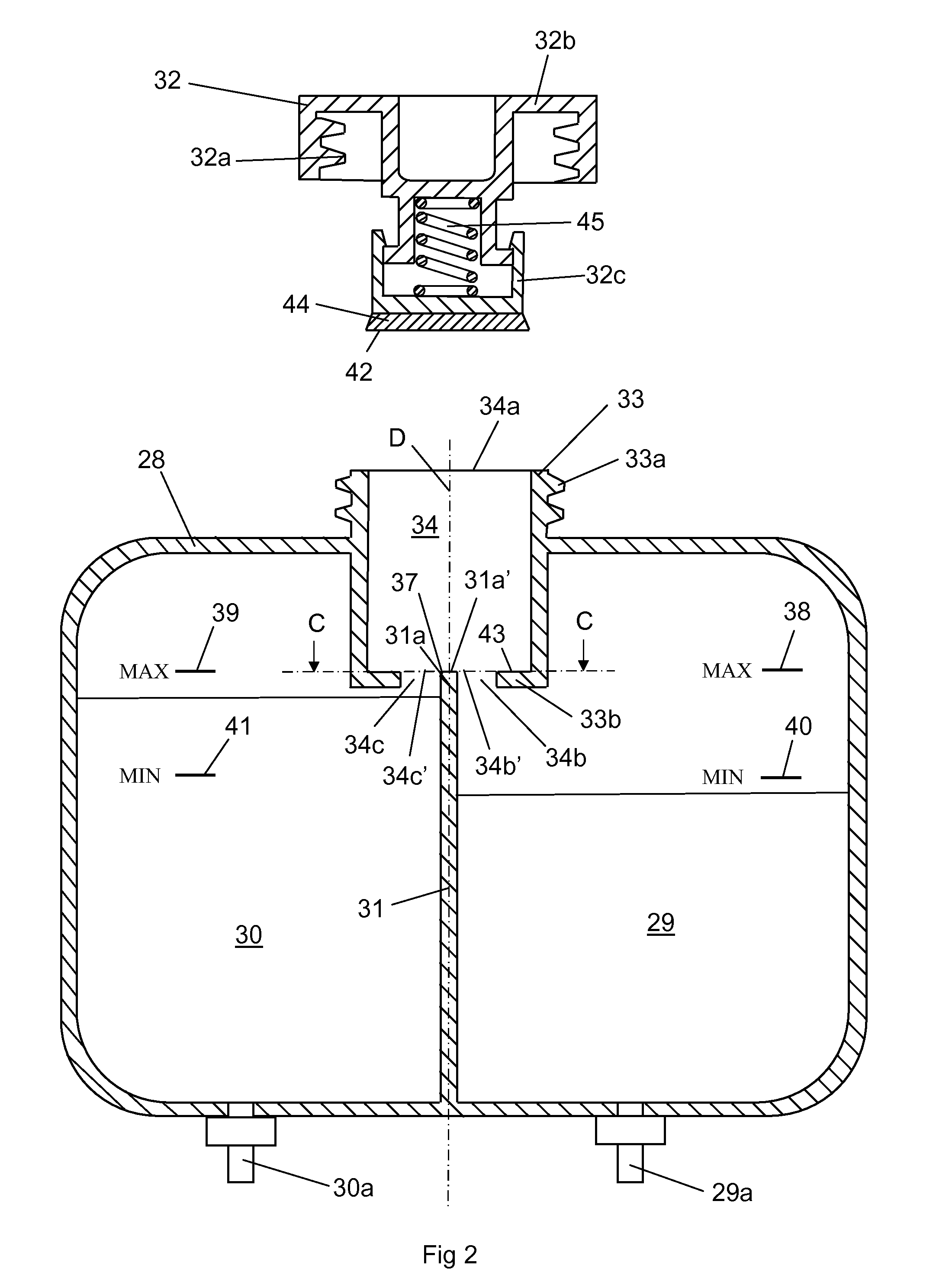
[0006]This object is achieved with the arrangement of the kind mentioned in the introduction which is characterised by the features indicated in the characterising part of claim 1. It is assumed that the same type of liquid is used in both systems. The expansion tank comprises two expansion chambers which are used for receiving coolant in two separate systems. The expansion tank comprises a passage with an inlet aperture for liquid replenishment of the respective expansion chambers. The passage has with advantage a slope downwards from the inlet aperture so that the liquid runs through the passage by force of gravity. The liquid runs initially through a common portion of the passage. At a distance from the inlet aperture, the passage divides into a first branch which leads liquid to the first expansion chamber and a second branch which leads liquid to the second expansion chamber. Such a passage makes it possible to replenish expansion chambers of two different systems at the same time with liquid from a single point.
[0009]According to another preferred embodiment of the invention, the cover comprises a closure element adapted to closing the first branch and / or the second branch when the cover is in the fitted state. As the cover in the fitted state closes at least one of said branches, there can be no transfer of liquid between the two branches, nor consequently between the two expansion chambers, when the systems are in operation. The two systems are thus completely separated from one another when the cover is in the fitted state. The closure element may comprise a contact surface adapted to coming into contact with at least a contact surface which defines an inlet aperture to the first branch and / or a contact surface which defines an inlet aperture to the second branch when the cover is in the fitted state. Appropriate configuration of said contact surfaces will result in good closure of the first branch and / or the second branch when the cover is in the fitted state. The expansion tank comprises with advantage at least one seal element which defines at least one of said contact surfaces. Such a seal element may be made of an elastic material, e.g. a rubber material. Very reliable closing of the first branch and / or the second branch may thus be achieved.
[0010]According to another preferred embodiment of the invention, the closure element is adapted to closing the first branch and / or the second branch with a flexible force. It is possible to use for the purpose a spring means applied in such a way that it presses the closure element against a contact surface with a spring force when the cover is in the fitted state. If the pressure in either of the expansion chambers rises to a level above a highest acceptable value, the closure element may lift against the action of the spring means so that the pressure within the expansion chamber is reduced. When the pressure in the expansion chamber is reduced to an acceptable level, the spring means will reclose the closure element.

Problems solved by technology

It is therefore not appropriate for the coolants to be mixed.

Method used


Image

  • Expansion tank
  • Expansion tank
  • Expansion tank

Examples


Embodiment Construction

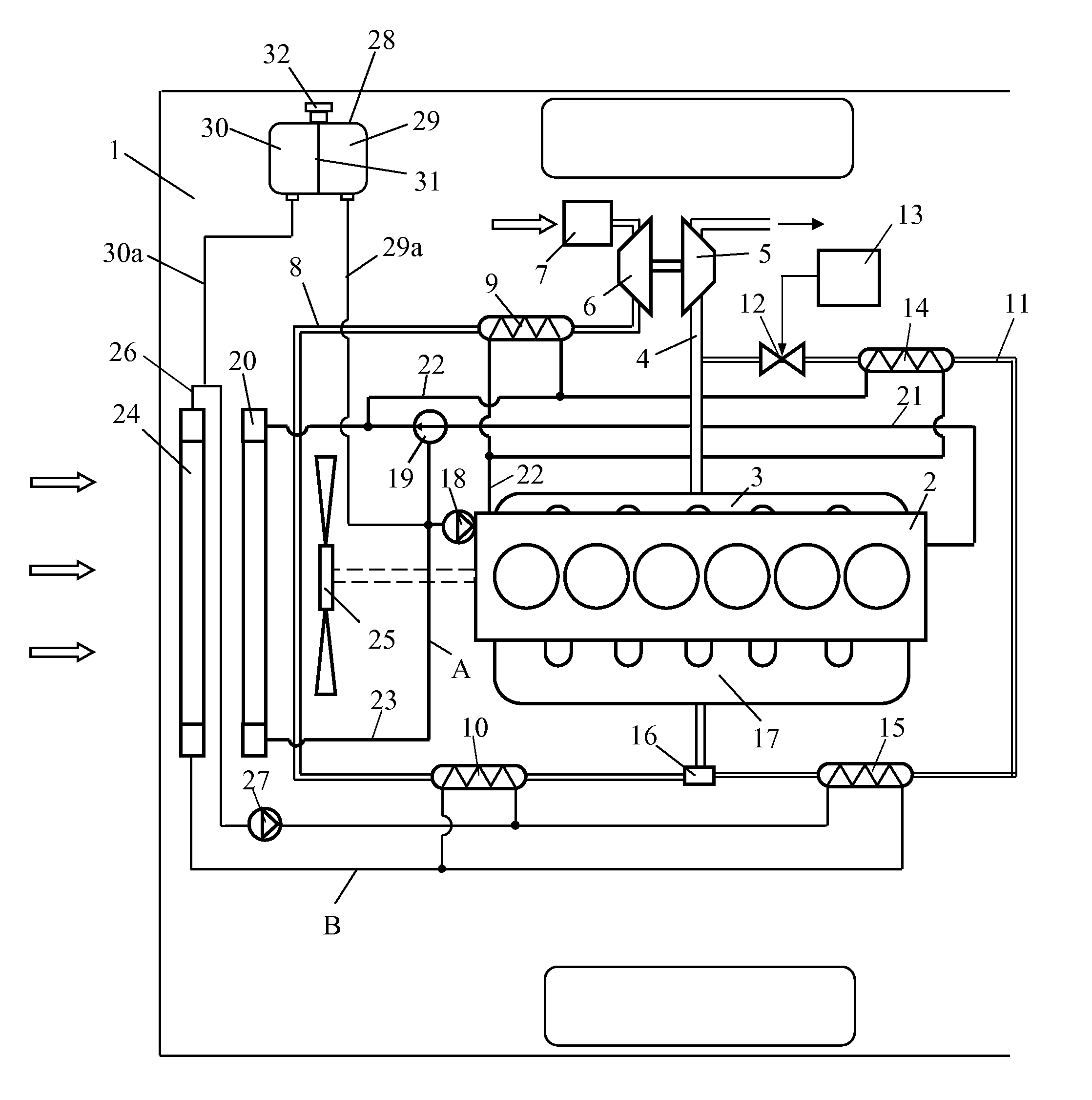
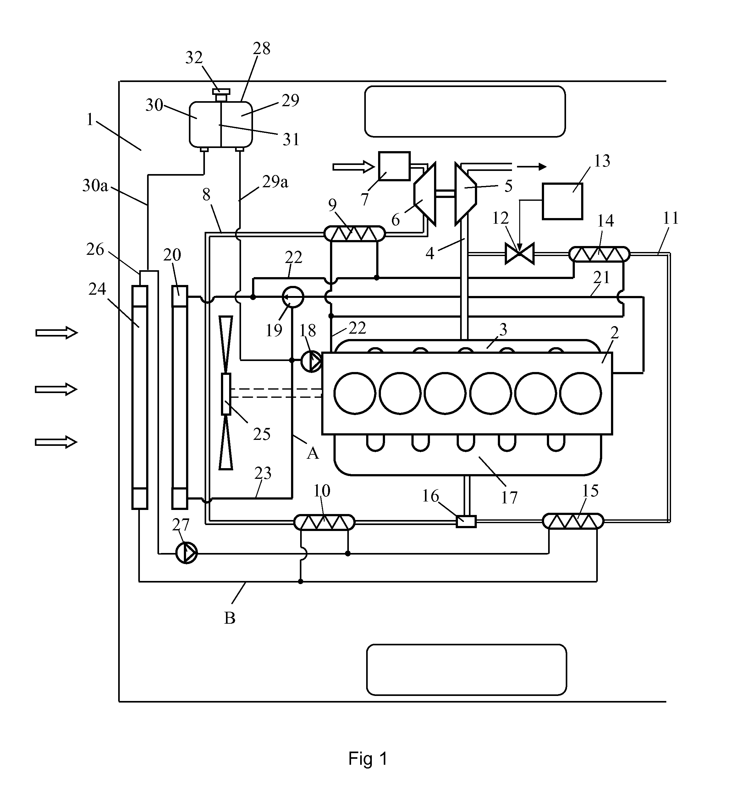
[0017]FIG. 1 depicts schematically a vehicle 1 powered by a supercharged combustion engine 2. The vehicle 1 is with advantage a heavy vehicle. The combustion engine is here exemplified as a diesel engine 2. The exhaust gases from the cylinders of the diesel engine 2 are led via an exhaust manifold 3 to an exhaust line 4. The diesel engine 2 is provided with a turbo unit which comprises a turbine 5 and a compressor 6. The exhaust gases in the exhaust line 4, which will be at above atmospheric pressure, are led initially to the turbine 5. The turbine 5 is thereby provided with driving force which is transferred, via a connection, to the compressor 6. The compressor 6 thereby compresses air which is drawn into an air inlet line 8 via an air filter 7. The air in the inlet line 8 is subjected to a first step of cooling in a first charge air cooler 9 by coolant from the combustion engine's cooling system A. The compressed air is thereafter subjected to a second step of cooling in a second...


PUM


Abstract

An expansion tank (28) comprising a passage (34) with a an inlet aperture (34a) for liquid replenishment of the expansion tank (28), a cover (32) which in a non-fitted state leaves the passage (34) clear and in a fitted state closes the passage (34), and a first expansion chamber (29) for receiving liquid which circulates in a first system (A). The expansion tank (28) includes a second expansion chamber (30) for receiving liquid which circulates in a second system (B) and said passage (34) divides, at a distance from the inlet aperture (34a), into a first branch (34b) which leads liquid to the first expansion chamber (29) and a second branch (34c) which leads liquid to the second expansion chamber (30).

Description

BACKGROUND TO THE INVENTION AND STATE OF THE ART[0001]The present invention relates to an expansion tank according to the preamble of claim 1.[0002]The amount of air which can be supplied to a supercharged combustion engine depends on the pressure of the air but also on the temperature of the air. Supplying as large an amount of air to the combustion engine as possible entails effective cooling of the air before it is led to the combustion engine. Effective cooling of the charge air may be achieved by subjecting it to two steps of cooling. The charge air may be subjected to a first step of cooling in a first charge air cooler by coolant from the combustion engine's cooling system. This first step may cool the charge air to a temperature close to the temperature of the coolant. The charge air may thereafter be subjected to a second step of cooling in a second charge air cooler by coolant from a low-temperature cooling system. The charge air may thus be cooled to a temperature close t...

Claims


Application Information

Patent Timeline
IPC IPC(8): B65D1/24
CPCF01P11/029F01P11/02F01P11/00F01P3/20
Inventor KARDOS, ZOLTANSODERBERG, ERIK
Owner SCANIA CV AB
Features
  • Generate Ideas
  • Intellectual Property
  • Life Sciences
  • Materials
  • Tech Scout
  • Unparalleled Data Quality
  • Higher Quality Content
  • 60% Fewer Hallucinations
Learn More