Using image sensor and tracking filter time-to-go to avoid mid-air collisions

a technology of image sensor and tracking filter, applied in the direction of direction finders, instruments, aircraft traffic control, etc., can solve the problems of high uncertainty in ttc estimates, and drawbacks of each of the above principles for estimating ttc, etc., and achieve high degree of certainty

Active Publication Date: 2011-09-01
SAAB AB
View PDF5 Cites 66 Cited by
  • Summary
  • Abstract
  • Description
  • Claims
  • Application Information

AI Technical Summary

Benefits of technology

[0007]It is an object of the present invention to provide a collision avoidance system which is able to predict the time to collision (TTC) between an aerial vehicle equipped with the system and an intruding aerial vehicle with a high degree of certainty.
[0014]By using the TTCIPU estimates as input parameters to the tracking filter, the present invention provides a collision avoidance system benefitting from both the advantage offered by conventional tracking filters (TTC estimates available even when the target is far distant) and the advantage offered by conventional image sensors using scale correlation techniques (high degree of certainty in TTC estimates when the target is nearby).
[0015]An advantage of running the TTCIPU estimates through the tracking filter instead of simply using TTCTF estimates from the tracking filter at long distances and TTCIPU estimates from the image processing units at short distances, is that the use of the TTCIPU estimates as input parameters to the filter has a positive impact not only on the TTCTF estimates outputted by the filter but also the other state parameters of the filter model. For example, a tracking filter is typically designed to estimate the distance to the intruding vehicle in order to establish the three-dimensional position thereof. By providing the TTCIPU estimates as input to filter, both the distance estimation and the distance uncertainty estimation computed by the filter can be substantially improved.
[0016]The time to manoeuvre (TTM), i.e. the time left until an avoidance manoeuvre must be performed in order to avoid collision, is typically calculated based on a plurality of parameters, of which the TTC estimate and its associated uncertainty are two very important ones. The present invention thus provides for a more robust collision avoidance system where the number of avoidance maneuvers performed without due cause can be minimized since the principle of using TTCIPU estimates from the image processing unit as input parameters to the tracking filter reduces the uncertainty in the TTCTF estimates outputted by the filter.
[0018]According to another embodiment of the invention, the CA means is arranged to make the decision as to whether or not the collision avoidance manoeuvre should be performed based on either or both of a parameter indicative of the TTCTF estimate outputted by the tracking filter and a parameter indicative of TTCIPU estimate made by the image processing means. Preferably, the CA means is, in this case, arranged to compare the TTCTF estimate with the TTCIPU estimate and make the decision based on the estimate indicating the shortest time to collision. This adds another layer of safety to the collision avoidance system according to the invention.
[0022]It is another object of the present invention to provide a method for deciding whether an avoidance manoeuvre should be performed in order to avoid a mid-air collision between a host aerial vehicle and an intruding aerial vehicle.

Problems solved by technology

However, each of the above principles for estimating TTC suffer from drawbacks.
The second principle according to which TTC estimates are estimated by a tracking filter suffers from the drawback that the uncertainty in the TTC estimates is high.
The uncertainty in the TTCIPU estimates is typically high as long as the intruding vehicle is far distant to the host vehicle.

Method used


Image

  • Using image sensor and tracking filter time-to-go to avoid mid-air collisions
  • Using image sensor and tracking filter time-to-go to avoid mid-air collisions
  • Using image sensor and tracking filter time-to-go to avoid mid-air collisions

Examples


Embodiment Construction

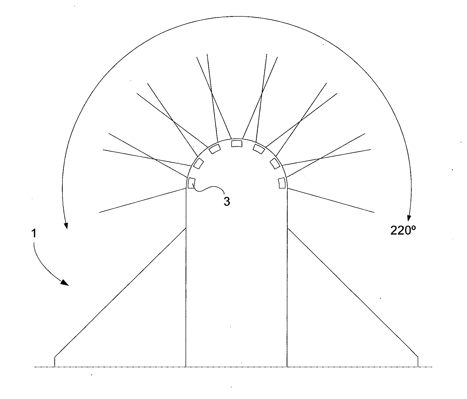
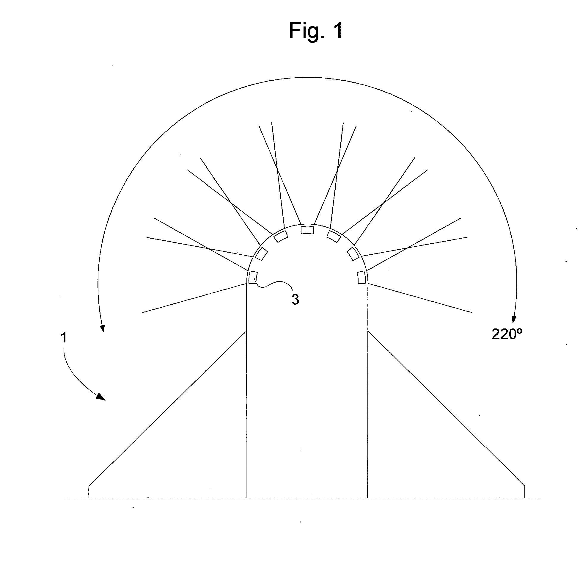
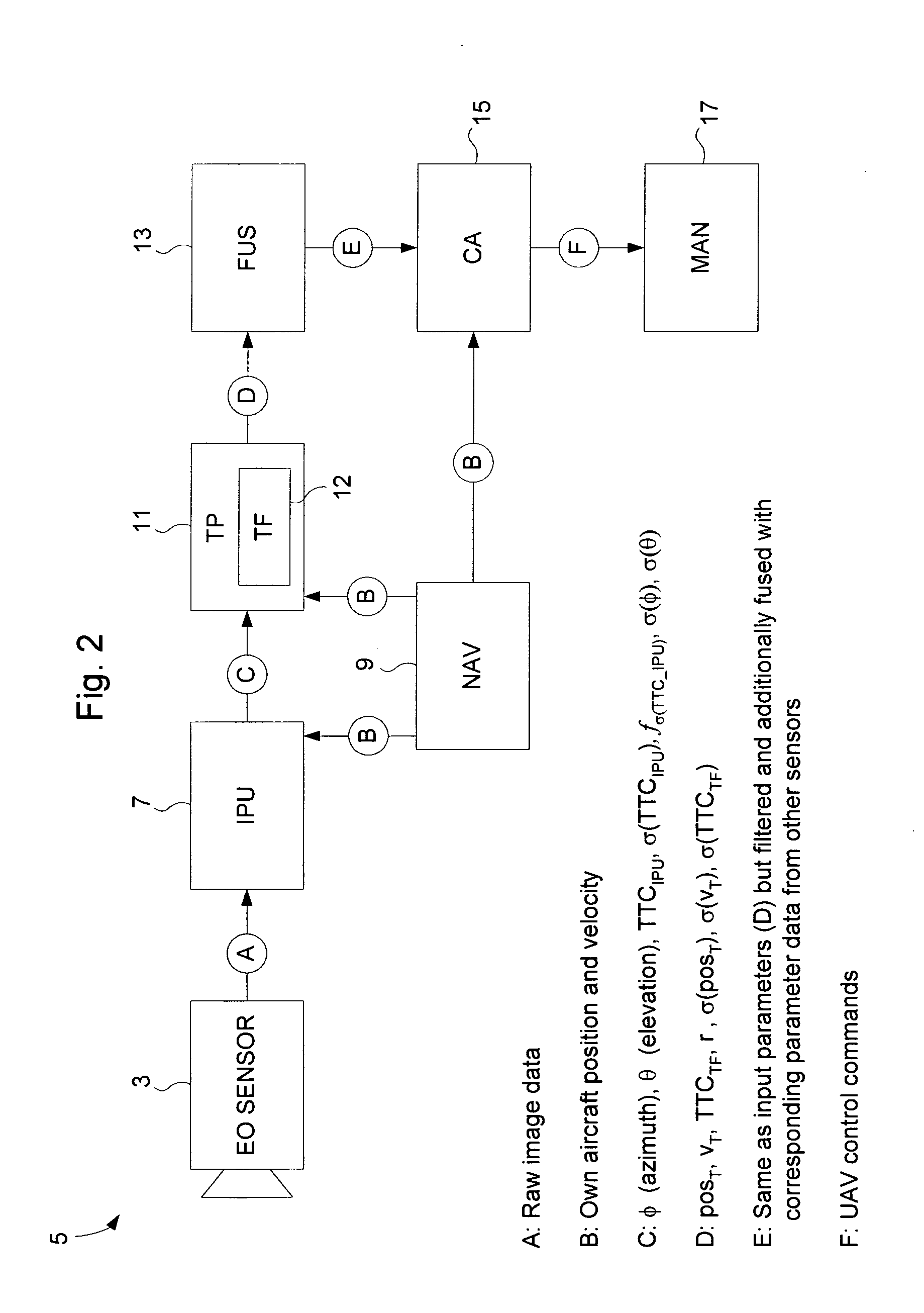
[0035]FIG. 1 illustrates a top view of the front half of an Unmanned Aerial Vehicle (UAV) 1. The UAV 1 comprises one or several electro-optical (EO) sensors 3 for monitoring surrounding air traffic. The EO sensors 3 constitute parts of a tracking system for continuously tracking nearby airborne objects in order to avoid midair collisions. The collision avoidance system of which the tracking system forms a part will be described in more detail below with reference to FIG. 2.

[0036]In the exemplary embodiment illustrated in FIG. 1, the UAV 1 is seen to comprise seven electro-optical (EO) sensors 3 which are arranged in a semi-circular pattern on or close to the nose of the UAV 1. The EO sensors 3 may be any devices which are able to capture consecutive images of objects in the surrounding airspace. In one embodiment of the invention, the EO sensors 3 are 9 Hz video cameras 3 capturing images having a 2048×2048 pixel resolution. That is, each camera 3 captures nine high-resolution image...


PUM


Abstract

A collision avoidance system for deciding whether an autonomous avoidance manoeuvre should be performed in order to avoid a mid-air collision between a host aerial vehicle equipped with the system and an intruding aerial vehicle. At least one electro-optical sensor captures consecutive images of an intruding vehicle such that the vehicle manifests itself as a target point in the images. An image processor estimates the azimuth angle, elevation angle and a first time-to-collision estimate of the time to collision between the host vehicle and the intruding vehicle. The first time-to-collision estimate is estimated based on scale change in the target point between at least two of said consecutive images. A tracking filter is arranged to estimate a second time-to-collision estimate using the azimuth angle, the elevation angle and the first time-to-collision estimate estimated by the image processor as input parameters. A collision avoidance module is arranged to decide whether or not an avoidance manoeuvre should be performed based on any of at least one parameter, of which at least one is indicative of said second time-to-collision estimate.

Description

TECHNICAL FIELD[0001]The present invention relates to the field of mid-air collision avoidance, and more particularly to a system and method for deciding whether or not an aerial vehicle should perform an autonomous avoidance manoeuvre in order to avoid collision with another aerial vehicle.BACKGROUND ART[0002]In order to allow unmanned aerial vehicles (UAVs) to travel in civil unsegregated airspace, several technical problems must be solved. One of the most important issues is the “sense & avoid” problem: a UAV must be able to sense the presence of other aerial vehicles and, if necessary, perform an autonomous and safe last instant manoeuvre to avoid mid-air collision. Therefore, a UAV typically comprises an air collision avoidance system, sometimes also referred to as a Sense & Avoid system, including one or several sensors for sensing intruding aircraft, and collision avoidance functionality that uses the sensed data and the performance characteristics of the own aircraft to perf...

Claims


Application Information

Patent Timeline
Patent Type & Authority Applications(United States)
IPC IPC(8): G08G5/04G01S13/933
CPCG01S3/7864G08G5/045G01S11/12G01S5/16
Inventor MOLANDER, SOREN
Owner SAAB AB
Why Eureka
Try Eureka