
Compact automated cell counter

a cell counter and compact technology, applied in the field of hemocytometry and systems, can solve the problems of inability to accurately count cells, etc., to achieve low cost, low cost, and low cost

Active Publication Date: 2011-09-01
BIO RAD LAB INC
View PDF15 Cites 34 Cited by
  • Summary
  • Abstract
  • Description
  • Claims
  • Application Information

AI Technical Summary

Benefits of technology

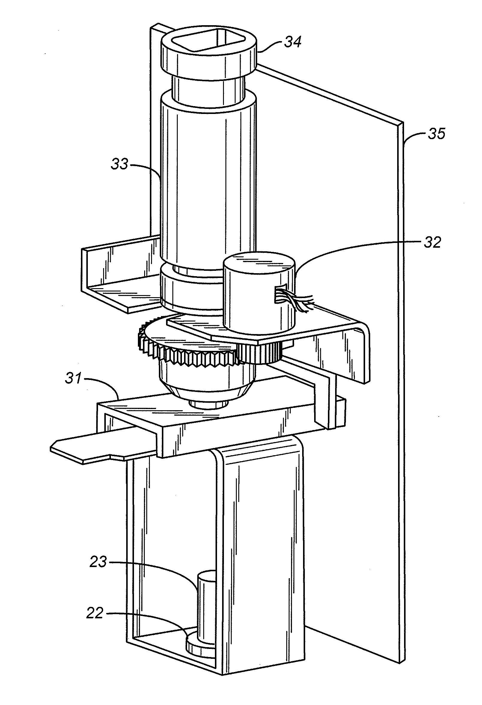
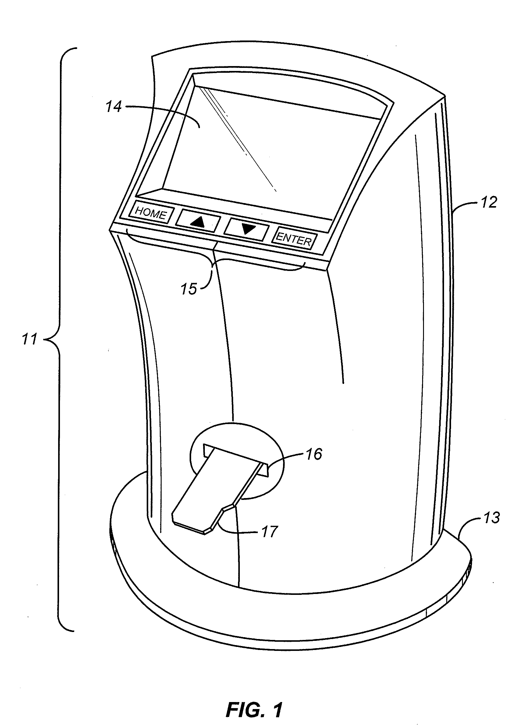
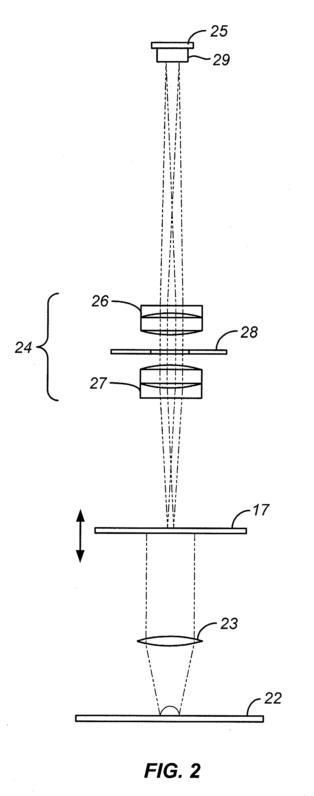
[0008]Disclosed herein is a fully self-contained instrument for highly accurate cell counting with minimal user intervention as well as a relatively small footprint and limited height. A cell suspension is placed in a consumable sample vessel whose size and dimensions can vary widely, one convenient example of which is a vessel whose outer dimensions are similar to those of a microscope slide. The vessel can thus be similar in construction and dimensions to the vessel described in US 2006 / 0223165 A1 referenced above, with at least one flat, shallow internal chamber bounded on the top and bottom by flat, optically clear windows, which can be plastic sheets, whose spacing is close enough that most of the cells of the sample form a layer that is one cell deep. Appropriate inlet and vent ports can be included in the vessel to allow the chamber to be easily and completely filled with the sample. The vessel is then placed in the instrument where it intersects a linear optical path. The term “linear” as used herein denotes a path with no turns or other changes in direction of the light beams other than those caused by lenses. The vessel enters the instrument through a slot at a designated height in the optical path, and as described below in greater detail, the instrument in certain embodiments of the invention contains features that automatically adjust the height of the sample for purposes of focusing the sample image. Certain embodiments contain features that cause all instrument functions to begin operation upon the insertion of the sample vessel into the instrument.

Problems solved by technology

A description of such a grid and the procedure for its use is found in Qiu, J., U.S. Pat. No. 7,329,537 B2, issued Feb. 12, 2008, “Micro-Pattern Embedded Plastic Optical Film Device for Cell-Based Assays.” Regardless of how it is done, manual cell counting is tedious and highly vulnerable to user error.
Automated cell counting systems themselves contain an inherent statistical uncertainty due to what is commonly referred to as “sampling error,” which refers to the error inherent in selecting the area in which the automated counting is performed.
One of the limitations of automated cell counters that are currently available is that due to the limitations of the optical components in the instruments, the area in which cells are counted is of limited size compared to the entire area occupied by the sample.
This presents disadvantages to the user, particularly when the instrument is to be used in a cell culture hood.

Method used


Image

  • Compact automated cell counter
  • Compact automated cell counter
  • Compact automated cell counter

Examples


Embodiment Construction

[0014]The upper and lower optical windows between which the cell suspension is retained inside the sample vessel are close enough that the retained suspension is a thin film whose lateral dimensions, i.e., its exposed length and width, are at least an order of magnitude greater that its thickness. The entire exposed area (i.e., lateral dimensions) of the sample chamber or a laterally dimensioned portion thereof serves as a field of view that is projected onto a digital imaging sensor that contains at least about 4,000,000 (four million) pixels, or in certain embodiments from about 4,000,000 to about 10,000,000 pixels, with each pixel being no greater than about 2×2 μm (4 μm2) in size, or from about 0.5×0.5 μm (0.25 μm2) to about 2×2 μm (4 μm2) in certain embodiments, and in certain of the latter from about 1×1 μm (1 μm2) to about 2×2 μm (4 μm2). The field of view imaged by the sensor is at least about 3 square millimeters, and often from about 3 mm2 to about 10 mm2. A complementary ...


PUM

PropertyMeasurementUnit
areaaaaaaaaaaa
areaaaaaaaaaaa
heightaaaaaaaaaa

Abstract

Biological cells in a liquid suspension are counted in an automated cell counter that focuses an image of the suspension on a digital imaging sensor that contains at least 4,000,000 pixels each having an area of 2×2 μm or less and that images a field of view of at least 3 mm2. The sensor enables the counter to compress the optical components into an optical path of less than 20 cm in height when arranged vertically with no changes in direction of the optical path as a whole, and the entire instrument has a footprint of less than 300 cm2. Activation of the light source, automated focusing of the sensor image, and digital cell counting are all initiated by the simple insertion of the sample holder into the instrument. The suspension is placed in a sample chamber in the form of a slide that is shaped to ensure proper orientation of the slide in the cell counter.

Description

CROSS-REFERENCE TO RELATED APPLICATION[0001]This application claims the benefit of U.S. Provisional Patent Application No. 61 / 238,534, filed Aug. 31, 2009, the contents of which are incorporated herein by reference.BACKGROUND OF THE INVENTION[0002]1. Field of the Invention[0003]This invention lies in the field of hemocytometry and systems in general for the counting of biological cells suspended in fluids. The focus of this invention is on automated cell counting systems.[0004]2. Description of the Prior Art[0005]Cell counting is of interest in a variety of clinical and research procedures, including the counting of leukocytes and erythrocytes, which is of value in the diagnosis of various diseases or abnormal conditions and in the monitoring of patients that are undergoing treatment for such diseases or conditions. Cells can be counted manually by placing a known dilution of a sample between optically clear plates that are sufficiently close to each other (typically with a spacing ...

Claims


Application Information

Patent Timeline
Patent Type & Authority Applications(United States)
IPC IPC(8): G06K9/00C12M1/00H04N7/18
CPCG01N15/1434G02B21/34G02B21/0008C12Q1/06
Inventor MCCOLLUM, TOMPATT, PAULSHEN, FRANKCHU, DANIEL Y.FLORY, DONGRIFFIN, MIKEHENG, XINHEFNER, ELI
Owner BIO RAD LAB INC
Learn More