Rod for supporting components in a fuselage cell structure of an aircraft

a technology for supporting components and fuselage cells, which is applied in the direction of fuselages, yarn, transportation and packaging, etc., can solve the problems of increasing the repair cost of known cfrp components, difficult to detect cracks and/or delaminations, and virtually impossible open repair, etc., to achieve high peak crash load and accident load

Inactive Publication Date: 2011-09-01
AIRBUS OPERATIONS GMBH
View PDF2 Cites 12 Cited by
  • Summary
  • Abstract
  • Description
  • Claims
  • Application Information

AI Technical Summary

Benefits of technology

[0012]The object of the invention is therefore to provide a supporting rod which is significantly lighter than known embodiments, but which is able to considerably reduce, as a result of plastic deformation, the high peak crash loads and accident loads of an aircraft which occur in the event of an aircraft accident.
[0014]Since the rod is formed at least in portions by a metal foam, in particular for the absorption of crash loads, the rod according to the invention is considerably lighter than conventional supporting rods, the capacity for absorbing of high mechanical peak loads in the event of an aircraft accident also being improved compared to supporting rods made of a solid, extruded metal material.
[0016]In an advantageous configuration of the rod the metal foam is formed by a metal alloy. The use of aluminium alloys for the metal foam used makes it possible to achieve an additional weight reduction as a result of the lightweight aluminium alloy material alongside the desired reduction in weight obtained by the cavities integrated into the metal matrix of the metal foam. Furthermore, in terms of manufacture, aluminium alloy materials can be rather easily foamed owing to their relatively low melting point of approximately 700 ° C., so cost-effective production is possible.
[0018]In terms of manufacture a particularly simple and cost-effective construction of the rod is thus achieved. Furthermore, the end metal fittings can be fastened more easily to a solid metal foam cylinder.
[0019]In accordance with a further development an outer face of the rod is closed-cell or open-cell. In particular the closed-cell variant affords the advantage that moisture and / or particles of dirt cannot infiltrate the rod, in such a way that corrosive effects can be eliminated, in particular for aluminium alloys, whilst in the open-pore or open-cell embodiment the aforementioned effects cannot be entirely prevented, but a drainage capability is provided in the region of the rod close to the surface for any foreign materials that have already infiltrated.
[0021]As a result of this configuration it is possible for the normal stresses occurring during flight operation to be substantially absorbed by the support casing and also additionally by the outer sleeve, whilst the high mechanical peak loads which occur in a crash situation are eliminated almost exclusively by a plastic deformation of the metal foam core. Furthermore, uncontrolled buckling of the metal foam core in the event of a crash is prevented by the support casing in such a way that the kinetic energy is absorbed almost exclusively by the compression of the cavities contained in the metal foam and the energy is absorbed almost exclusively in a longitudinal direction of the rod. In addition, the infiltration of moisture and / or foreign particles into the metal foam core is prevented by the outer sleeve in such a way that undesired effects of corrosion, which may be detrimental to mechanical strength and / or the ability to absorb kinetic energy, are eliminated.

Problems solved by technology

However, a drawback is the increased repair cost of known CFRP components.
Open repair is virtually impossible in the event of mechanical damage caused by the impact of stones or the like.
In addition, it is difficult to detect cracks and / or delaminations in CFRP components since these defects often start within the material and, in the early stages, can only be detected on the surface with difficulty.
A further drawback is that modern CFRP materials are only slightly resiliently deformable as a result of their extremely high level of mechanical rigidity, so the mechanical peak loads (‘crash loads’) which occur in the event of an accident, which are short in duration but are nevertheless very strong, cannot be sufficiently reduced.
In such critical situations, known CFRP materials tend to be increasingly likely to splinter or break completely once the mechanical limit load has been reached.
In some cases the crash loads may even be increased as a result of the spring action of the CFRP materials.
Compared to the conventional components of a CFRP fuselage cell, however, such supporting rods made of extruded aluminium alloys are relatively heavy.
However, a drawback of this variant is the weight, since an additional absorption element for absorbing the impact energy is included but does not take up any stresses within the fuselage cell during normal operation.

Method used


Image

  • Rod for supporting components in a fuselage cell structure of an aircraft
  • Rod for supporting components in a fuselage cell structure of an aircraft
  • Rod for supporting components in a fuselage cell structure of an aircraft

Examples


Embodiment Construction

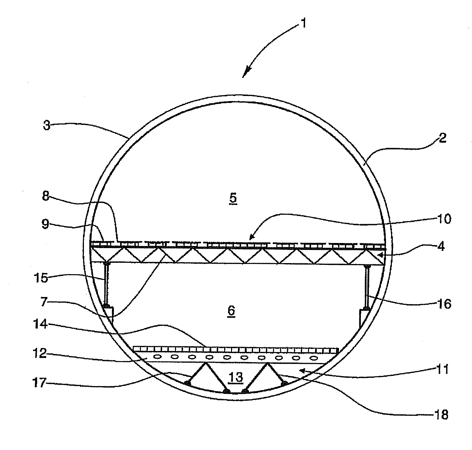
[0027]FIG. 1 is a cross-sectional view through a fuselage cell structure of an aircraft. A fuselage cell structure 1 of an aircraft comprises a large number of annular formers, of which one annular former 2 is provided with a reference numeral. The fuselage cell structure 1 is completely covered by an outer skin 3 or outer skin segments. The fuselage cell structure 1 further comprises a floor frame 4 which divides the fuselage cell structure 1 into a passenger cabin 5 and a generally smaller hold 6 arranged therebelow. The floor frame 4 is constructed with a large number of crossbars 7 which are each arranged in a plane transverse to the longitudinal direction of the aircraft, spaced approximately uniformly from one another and successively. On the crossbar 7 a seat rail 8 extends perpendicular to the drawing plane, i.e. parallel to the longitudinal axis of the aircraft, and parallel to a large number of further seat rails which, on the one hand, reinforce the floor frame 4 and, on ...


PUM

PropertyMeasurementUnit
melting pointaaaaaaaaaa
distanceaaaaaaaaaa
weightaaaaaaaaaa

Abstract

A rod for supporting components in a fuselage cell structure, in particular produced with fibre-reinforced composite materials, of an aircraft, in particular for supporting at least one floor frame on at least one annular former and / or at least one further component of the fuselage cell structure.In accordance with the invention the rod is formed, at least in portions, with a metal foam, in particular for the absorption of crash loads.The metal foam can transform, irrespective of its inherent weight, the high mechanical loads produced in the event of an accident into work of plastic deformation at the microcavities within the metal foam.A first variant of the rod is almost completely formed by a metal foam, whereas a second embodiment comprises merely a core made of the metal foam with a relatively small diameter, which core is surrounded coaxially by a support casing and an outer sleeve.

Description

CROSS-REFERENCE TO RELATED APPLICATIONS[0001]This application is a continuation of PCT / EP2009 / 061060 filed Aug. 27, 2009 and claims the benefit of U.S. Provisional Application No. 61 / 191,879, filed Sep. 12, 2008 and German Patent Application No. 10 2008 042 036.0, filed Sep. 12, 2008, the entire disclosures of which are herein incorporated by reference.FIELD OF THE INVENTION[0002]The invention relates to a rod for supporting components in a fuselage cell structure, in particular produced with fibre-reinforced composite materials, of an aircraft, in particular for supporting at least one floor frame on at least one annular former and / or at least one further component in the fuselage cell structure.[0003]At least one floor frame is generally integrated into a fuselage cell structure of a passenger aircraft and is formed, inter alia, by a large number of transverse crossbars arranged successively and extending transverse to the direction of flight, as well as with seat rail profiled pa...

Claims


Application Information

Patent Timeline
Patent Type & Authority Applications(United States)
IPC IPC(8): B32B3/06B64C1/18B64C1/06B32B3/26B32B3/12
CPCB64C1/062B64C1/18Y10T428/2929Y10T428/24008Y10T428/24149Y10T428/249953Y10T428/249987
Inventor BUELLESBACH, TIM
Owner AIRBUS OPERATIONS GMBH
Why Eureka
Try Eureka