Method, apparatus and system for estimating channels
- Summary
- Abstract
- Description
- Claims
- Application Information
AI Technical Summary
Benefits of technology
Problems solved by technology
Method used
Image


Examples
first embodiment
[0044]a channel estimation method is described below:
[0045]FIG. 2 is a flowchart of a channel estimation method provided in the first embodiment of the present invention. The method includes the following steps:
[0046]Step 101: Receive downlink signals inclusive of reference signals from two or more APs, where a relative frequency shift between reference signals sent by different APs is zero.
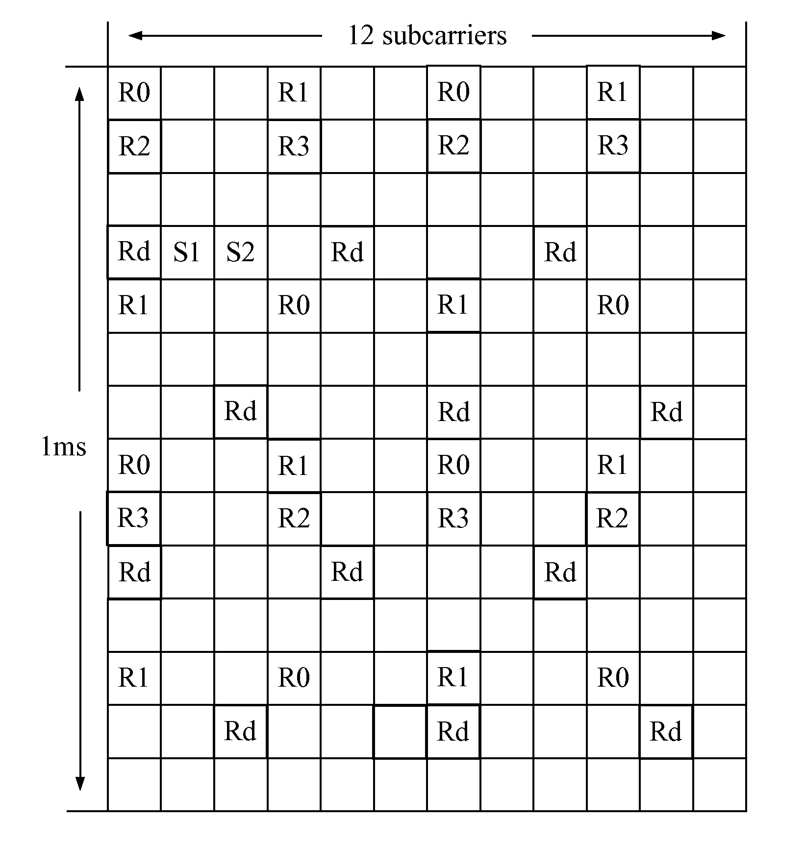
[0047]When this embodiment is applied in a CoMP system, the UE receives the downlink signals sent by two or more cooperative APs. This embodiment changes the mode of the reference signals shown in FIG. 1A and FIG. 1B so that no relative frequency shift exists between the reference signals sent by different APs, namely, the relative frequency shift is zero. The cooperative APs send the reference signals to the UE according to the sending mechanism corresponding to the changed reference signals, and the UE receives the reference signals according to the receiving mechanism corresponding to the chan...
second embodiment
[0051]a channel estimation method is described below:
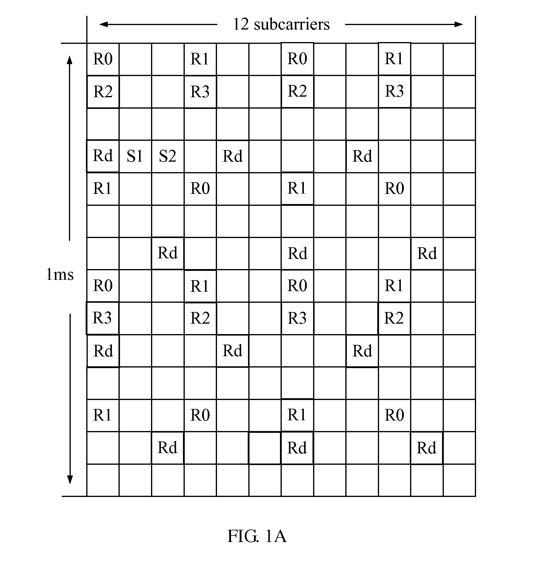
[0052]FIG. 3A and FIG. 3B show reference signals of a first AP and a second AP respectively in a channel estimation method in the second embodiment of the present invention. The processing method in this embodiment is the same as that in the first embodiment above. This embodiment gives details about how to change the mode of the reference signals.
[0053]Dedicated reference signals are taken as an example here. It is assumed that any two APs among two or more APs are a first AP and a second AP. The two APs are the cooperative APs that serve the same UE. FIG. 3A and FIG. 3B show the reference signals of the first AP and the second AP respectively. In comparison with FIG. 1B, the frequency shift of the dedicated reference signals of the second AP in FIG. 3B has changed. No relative frequency shift exists between the dedicated reference signal of the first AP and that of the second AP, namely, the relative frequency shift between the ...
third embodiment
[0057]a channel estimation method is described below:
[0058]The processing method in this embodiment is the same as that in the first embodiment above. Specifically, the reference signal is a dedicated reference signal; in the same way as obtaining the dedicated reference signal in the second embodiment above, this embodiment can obtain the dedicated reference signal whose relative frequency shift is zero. Differently, this embodiment uses an interference elimination method to eliminate the interference between the common reference signal and the data signal.
[0059]FIG. 4 is a flowchart of a channel estimation method provided in the third embodiment of the present invention. On the basis of the first embodiment, step 102 may include the following steps:
[0060]Step 1021: Regard data signals in the downlink signals as interference signals, and perform channel estimation.
[0061]The data signals may be regarded as interference signals to perform channel estimation.
[0062]Step 1022: Estimate ...
PUM
 Abstract
Description
Claims
Application Information
 - Generate Ideas
- Intellectual Property
- Life Sciences
- Materials
- Tech Scout
- Unparalleled Data Quality
- Higher Quality Content
- 60% Fewer Hallucinations
Browse by: Latest US Patents, China's latest patents, Technical Efficacy Thesaurus, Application Domain, Technology Topic, Popular Technical Reports.
© 2025 PatSnap. All rights reserved.Legal|Privacy policy|Modern Slavery Act Transparency Statement|Sitemap|About US| Contact US: help@patsnap.com