Control system of hybrid vehicle

Inactive Publication Date: 2011-09-01
NISSAN MOTOR CO LTD
View PDF4 Cites 20 Cited by
  • Summary
  • Abstract
  • Description
  • Claims
  • Application Information

AI Technical Summary

Benefits of technology

[0006]It is an object of the invention to provide a control system of a hybrid vehicle which control system is capable of preventing a motor travel distance (rec

Problems solved by technology

With this, at a “travel mode” in the key-on state, a power consumption by the motor is caused due to the engine lub

Method used


Image

  • Control system of hybrid vehicle
  • Control system of hybrid vehicle
  • Control system of hybrid vehicle

Examples


embodiment 1

[0014]At first, a structure is to be set forth.

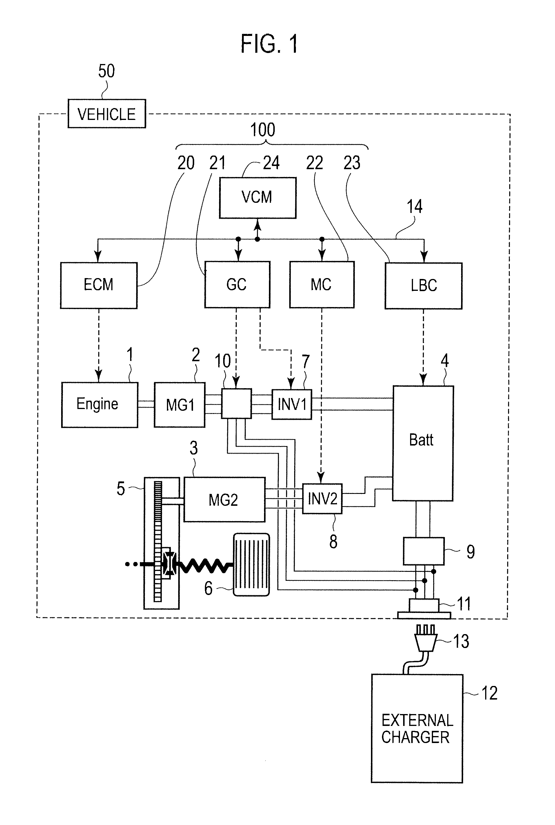
[0015]FIG. 1 is an entire system drawing showing a series type plug-in hybrid vehicle 50 (an example of a hybrid vehicle) to which a control system 100 is applied, according to an embodiment 1 of the present invention.

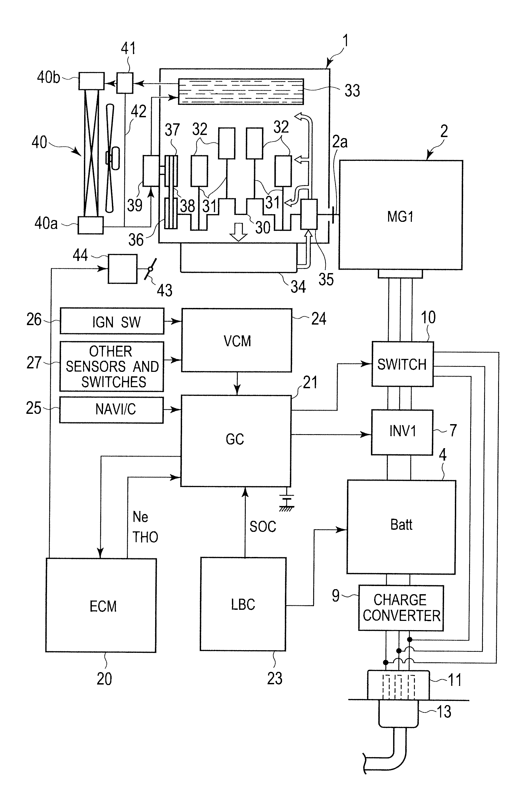
[0016]A drive system of the plug-in hybrid vehicle 50 according to the embodiment 1 is, as shown in FIG. 1, provided with an engine 1, a generation motor 2 (motor), a drive motor 3, a high power battery 4, a deceleration differential mechanism 5, a drive wheel 6, a generation motor inverter 7, a drive motor inverter 8, a charge converter 9, a switch 10 and a charge port 11.

[0017]The drive system of the embodiment 1 is of a series type (series method) where the engine 1 drives the generation motor 2, a generated power is stored in the high power battery 4, the power drives the drive motor 3 and the plug-in hybrid vehicle 50 travels with only the drive motor 3 as a driving source. In short, the plug-in hybrid vehicle 50 acco...


PUM


Abstract

A control system of a hybrid vehicle, includes: an engine; a motor capable of driving the engine; an oil pump for supplying a lubricant oil to a lubrication requiring portion of the engine; and an engine lubrication controller configured to make the following operations in a case that a stop state of the engine continues for more than or equal to a certain period: when a vehicle stop condition that a driver has no intention of travel is established, supplying, by the oil pump, the lubricant oil to the lubrication requiring portion of the engine, and rotating the engine by the motor without igniting the engine, thereby implementing an engine lubrication control.

Description

BACKGROUND OF THE INVENTION[0001]1. Field of the Invention[0002]The present invention relates to a control system of a hybrid vehicle where an engine and a motor capable of driving the engine is installed.[0003]2. Description of the Related Art[0004]As shown in Japanese Patent Application Laid-Open No. 2007-216764, a conventional hybrid vehicle equipped with a control system is known where the control system implements the following operations when a stop period of an engine goes beyond a certain period with an ignition key turned on (otherwise referred to as “key-on state”): without starting the engine, a cranking for rotating the engine by a motor drives a pump which circulates a lubricant oil in the engine.[0005]With respect to the conventional hybrid vehicle, however, when an oil lubrication requirement that the engine stop state has continued for more than or equal to the certain period is established in the ignition key-on state, cranking of the engine is implemented by the mo...

Claims


Application Information

Patent Timeline
IPC IPC(8): B60W20/00B60K6/20G06F19/00B60W10/06B60W10/30B60K6/28B60K6/46B60L50/15B60W10/26F02D29/02
CPCB60K6/46Y02T10/7275B60W30/18054B60W2510/30B60W2540/04Y02T10/6217Y02T10/6269F01M2001/0215B60L11/126B60L11/1877B60L15/20B60L2210/30B60L2210/40B60L2220/44B60L2240/421Y02T10/7077Y02T10/7005Y02T10/705Y02T10/7241Y02T10/642F01M2005/026B60W30/18018B60L50/62B60L50/66B60W2540/215Y02T10/62Y02T10/64Y02T10/70Y02T10/72B60K2006/268B60W50/082B60W50/085Y02T10/7072
Inventor ITO, TAKAOOOTAKE, YOSHIYUKIKOGA, MASAKIIWASAKI, TETSUYAOGINO, TAKASHIKONISHI, YASUHIROKOIKE, TOMOYUKISUZUKI, HIROYUKI
Owner NISSAN MOTOR CO LTD
Why Eureka
Try Eureka