Method for Increasing Security in a Passive Optical Network

a passive optical network and security technology, applied in the field of optical access networks, to achieve the effect of very low cost of authentication procedures

Active Publication Date: 2011-09-01
TELECOM ITALIA SPA
View PDF5 Cites 30 Cited by
  • Summary
  • Abstract
  • Description
  • Claims
  • Application Information

AI Technical Summary

Benefits of technology

[0041]According to the present invention, security in a passive optical network is increased by eliminating transmission of text passwords and / or encryption keys in cleartext over the optical access network, thus making possible eavesdropping of the traffic transmitted across the ODN (in particular, the uplink traffic) ineffective.
[0044]According to preferred embodiments of the present invention, a mechanism for generating an encryption key is further provided, that allows the OLT and the optical termination device (after successful mutual authentication) to independently generate the encryption key, without transmitting the encryption key through the passive optical network in cleartext.
[0046]Preferably, the method also provides a secure key updating mechanism for refreshing the encryption key. This is achieved by exchanging authenticated messages which allow the OLT and the optical termination device to independently generate a new encryption key without transmitting it through the passive optical network.
[0047]According to this mechanism for updating the encryption key, the OLT and the optical termination device preferably exchange authenticated data which, in combination with the secret code, allow both the OLT and the optical termination device to generate independently a new encryption key.
[0050]This advantageously allows avoiding the addition of other messages for performing the authentication mechanism and the mechanism for generating and updating the encryption key. This allows to keep the cost of the authentication procedure very low. This also advantageously allows not to change the authentication procedure as defined by the ITU-T Recommendation G.984.3 from the user point of view. This is advantageous, in that the user may still perform the same operations he used to perform during the known authentication procedure, without the need of learning any new authentication procedure. In other words, passing from the known authentication procedure defined by the ITU-T Recommendation G.984.3 to the authentication procedure according to the present invention is completely transparent to the user.

Problems solved by technology

Indeed, in all the above solutions, the information allowing the OLT to authenticate the optical termination device and / or to encrypt downlink transmission are transmitted uplink without providing any protection mechanism of these information, such as e.g. coding, encryption, etc.

Method used


Image

  • Method for Increasing Security in a Passive Optical Network
  • Method for Increasing Security in a Passive Optical Network
  • Method for Increasing Security in a Passive Optical Network

Examples


Embodiment Construction

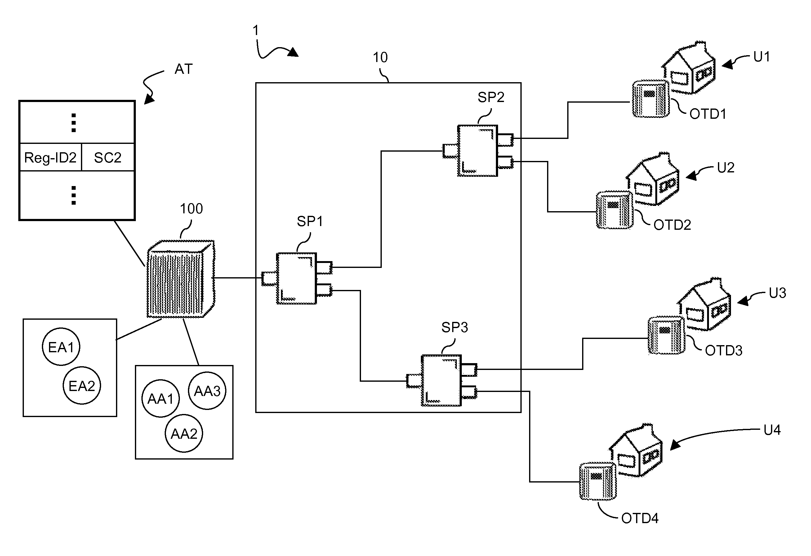
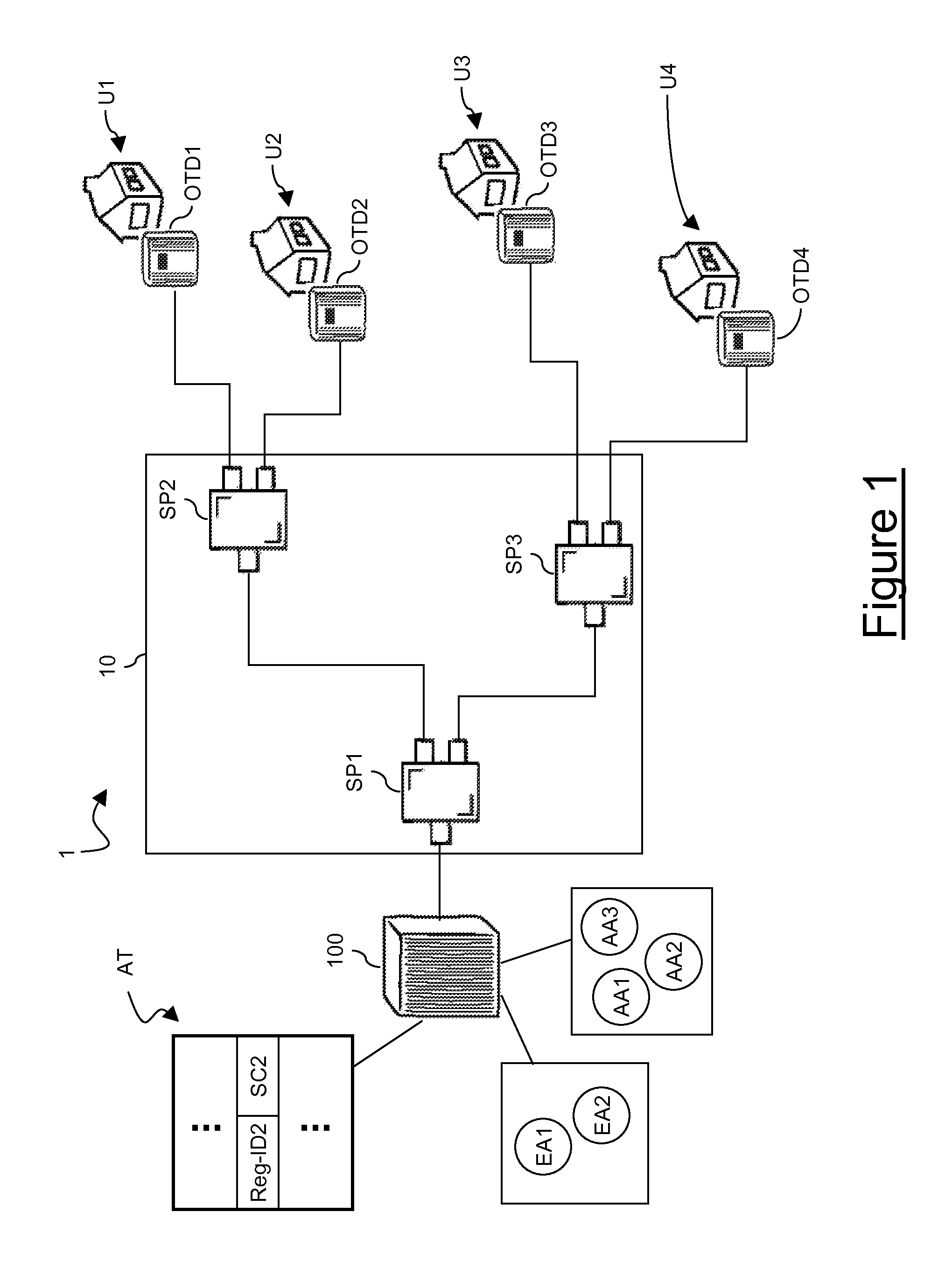
[0148]FIG. 1 schematically shows a PON 1 that, in the exemplary embodiment herein after described, is suitable for FTTH applications. However, the PON 1 may be used for other applications, such as for instance the above mentioned FTTB and FTTC applications. The PON 1 preferably comprises an ODN 10 and an OLT 100.

[0149]Preferably, the ODN 10 comprises three optical splitters SP1, SP2 and SP3. The optical splitter SP1 has an input optical link connected to the OLT 100 and two output optical links. The optical splitter SP2 has an input optical link connected to one of the output optical links of the optical splitter SP1 and two output optical links. Similarly, the optical splitter SP3 has an input optical link connected to the other output optical link of the optical splitter SP1 and two output optical links.

[0150]The ODN 10 shown in FIG. 1 is merely exemplary. Indeed, as mentioned above, an ODN typically comprises optical links and optical splitters arranged so as to form a point-mult...


PUM


Abstract

A method for security in a passive optical network is disclosed. The method includes, at an optical line termination (OLT): detecting an optical termination device and establishing a connection with the device; generating a first authentication message including a first random number; and transmitting the first authentication message through the established connection. At the optical termination device, the method may include: receiving the first authentication message; calculating a first authentication code by using the first random number and a secret code stored at the device; and generating and transmitting to the OLT a second authentication message including the first authentication code. The method may further include, at the OLT: receiving the second authentication message; calculating a second authentication code by using the first random number and a secret code stored at the OLT; and authenticating the optical termination device if the first authentication code matches the second authentication code.

Description

TECHNICAL FIELD[0001]The present invention generally relates to the field of optical access networks. In particular, the present invention relates to a method for increasing security in a passive optical network. Further, the present invention relates to an optical line termination, an optical termination device and a passive optical network suitable for implementing such a method.BACKGROUND ART[0002]Internet Protocol (IP) is becoming one of the most widespread protocols for implementing the network layer in a communication network. In particular, Next Generation Networks (briefly, NGNs) are known, i.e. packet-based networks using IP at their network layer. Such NGNs are able to make use of multiple broadband, QoS-enabled transport technologies, while service-related functions are independent of the underlying transport layer technologies. It is expected that NGNs will enable delivery to users of enriched communication services, such as for instance VoIP (Voice Over Internet Protoco...

Claims


Application Information

Patent Timeline
Patent Type & Authority Applications(United States)
IPC IPC(8): G06F21/00
CPCH04L63/06H04Q2011/0088H04Q11/0067H04L63/0869
Inventor COSTA, LUCIANAD'AMICO, ROBERTADE LUTIIS, PAOLOLEONE, MANUELVALVO, MAURIZIOSOLINA, PAOLO
Owner TELECOM ITALIA SPA
Why Eureka
Try Eureka