Propellant tank and vapor jet emitting device including same

a technology of vapor jet and propellant tank, which is applied in the direction of machines/engines, lighting and heating apparatus, domestic cooling apparatus, etc., can solve the problems of requiring a much greater amount of external thermal energy and cannot be lightweigh

Inactive Publication Date: 2011-09-08
JAPAN AEROSPACE EXPLORATION AGENCY +1
View PDF3 Cites 9 Cited by
  • Summary
  • Abstract
  • Description
  • Claims
  • Application Information

AI Technical Summary

Benefits of technology

The present invention has been made in consideration of the above problems. An object of the present invention is to provide a propellant tank which is lightweight and capable of supplying only vapor produced by evaporation of a propellant to an external location, and requires a smaller amount of external thermal energy, and a vapor jet emitting device including such propellant tank.

Problems solved by technology

The aforementioned prior-art propellant tank with weighty foamed metal filling approximately the whole interior of the tank body can store the liquid propellant in a state that it is held in pores of the foamed metal, but cannot be lightweight.
Further, the aforementioned prior-art propellant tank requires that heat be transferred to the whole mass of the foamed metal by heating with the heater in order to cause evaporation of part of the propellant, and thus, requires a much greater amount of external thermal energy than otherwise.
These are the problems with the prior art to which a solution is sought.

Method used


Image

  • Propellant tank and vapor jet emitting device including same
  • Propellant tank and vapor jet emitting device including same
  • Propellant tank and vapor jet emitting device including same

Examples


Embodiment Construction

With reference to the drawings attached, a propellant tank and a vapor jet emitting device according to the present invention will be described below.

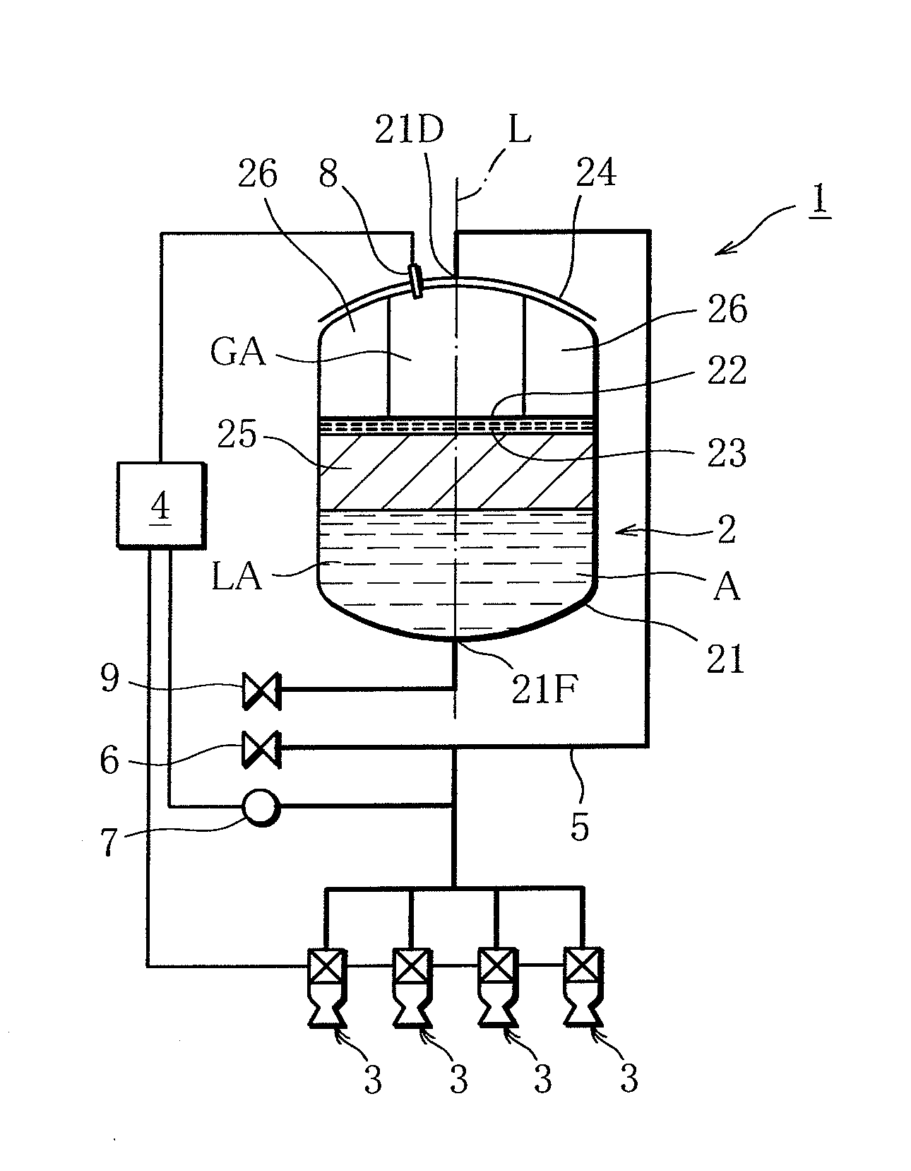
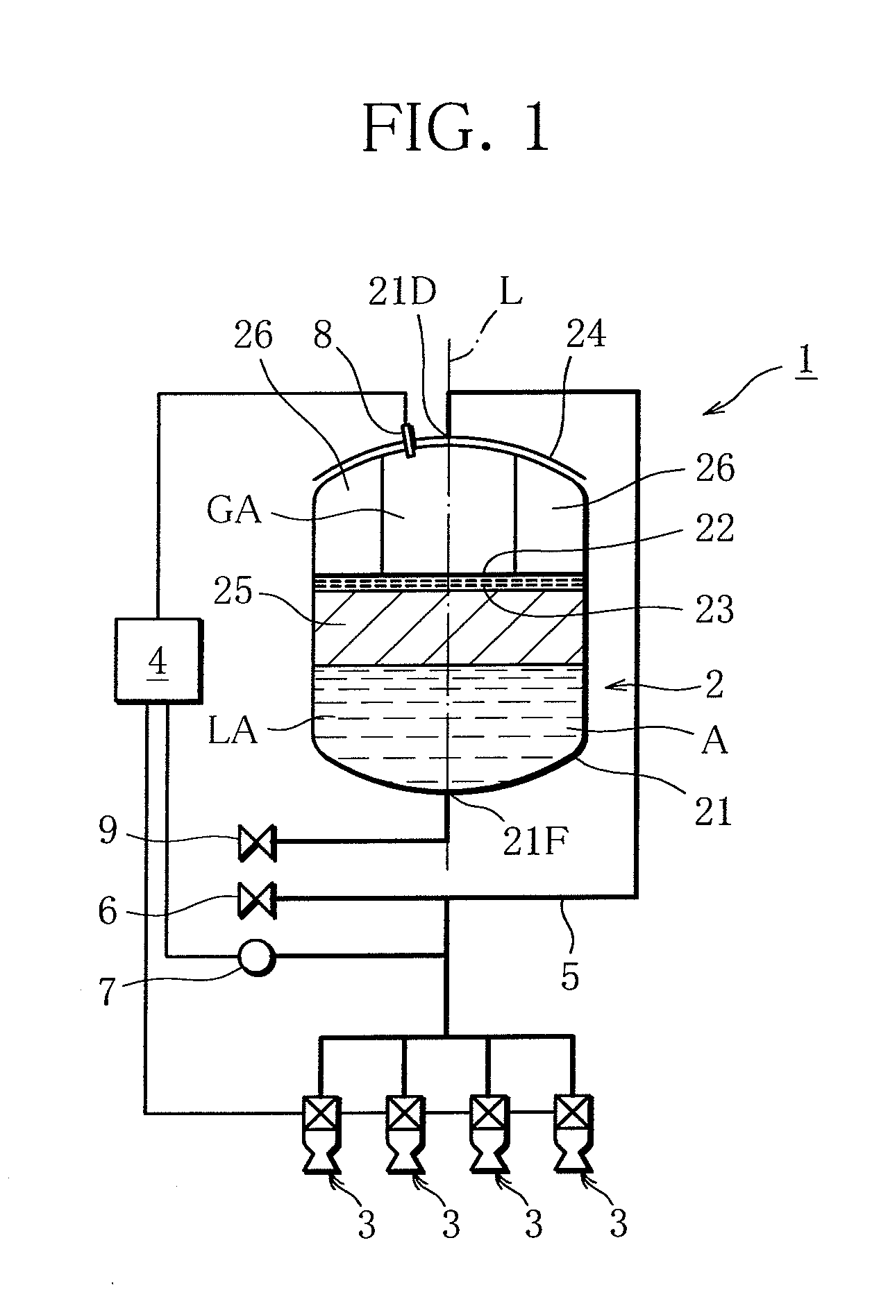
FIGS. 1 to 4 show a vapor jet emitting device including a propellant tank according to an embodiment of the present invention. Here, the embodiment of the present invention will be described with an example in which a vapor jet emitting device including a propellant tank is mounted on a spin-stabilized satellite.

As seen in FIG. 1, a vapor jet emitting device 1 comprises a propellant tank 2, a plurality of thrusters 3 and a control section 4 as main components.

The propellant tank 2 includes a cylindrical tank body 21 for storing a liquid propellant A. The tank body 21 is made of aluminum and has an axis L to be aligned with a spin axis of the spin-stabilized satellite. The tank body has a gas outlet 21D at the top and a propellant inlet 21F at the bottom, each located on the axis L. The terms “top” and “bottom” are used with respect to ...


PUM


Abstract

A propellant tank for storing a liquid propellant A and supplying vapor produced by evaporation of part of the liquid propellant A to an external location comprises a tank body for storing the liquid propellant A, a mesh member arranged inside the tank body to cover a liquid surface of the liquid propellant A to divide an interior of the tank body into a liquid propellant storing area LA and a gas storing area GA by utilizing surface tension of the liquid propellant, and a heater arranged to a gas storing area GA side of the tank body to keep the gas storing area GA at higher temperature than temperature in the liquid propellant storing area LA. The tank body has a propellant inlet open into the liquid propellant storing area LA and a gas outlet open into the gas storing area GA.

Description

BACKGROUND OF THE INVENTION1. Field of the InventionThis invention relates to a propellant tank mounted on, for example a spacecraft such as an artificial satellite to store a liquid propellant and supply vapor produced by evaporation of part of the liquid propellant to an external location, and a vapor jet emitting device for producing thrust by emitting a jet of the vapor supplied from the propellant tank.2. Description of the Related ArtA propellant tank of this type constituting the prior art is disclosed in Japanese Patent Application Preliminary Publication No. 2009-214695, for example.The propellant tank disclosed therein comprises a tank body for storing a liquid propellant, foamed metal filling approximately the whole interior of the tank body, and a heater surrounding the tank body. The tank body has a gas outlet. The tank body stores the liquid propellant in a state that the liquid propellant is held in pores of the foamed metal.This propellant tank is designed to cause e...

Claims


Application Information

Patent Timeline
Patent Type & Authority Applications(United States)
IPC IPC(8): F02K9/60B65D88/74
CPCB64G1/402F02K9/605F02K9/42
Inventor YAMAMOTO, TAKAYUKIMORI, OSAMUKISHINO, YOSHIHIROTAMURA, MASAYUKIKOGA, SHOHEIIMAI, RYOJI
Owner JAPAN AEROSPACE EXPLORATION AGENCY
Why Eureka
Try Eureka