Method and apparatus for the photo-acoustic identification and quantification of analyte species in a gaseous or liquid medium

US20110214479A1Inactive Publication Date: 2011-09-08LI COR
27 Cites 42 Cited by

Patent Information

Authority / Receiving Office
US · United States
Current Assignee / Owner
Publication Date
2011-09-08
Estimated Expiration
Not applicable · inactive patent

Smart Images

  • Figure 1
    Figure 1
  • Figure 2
    Figure 2
  • Figure 3
    Figure 3
Patent Text Reader

Abstract

A method and apparatus for the photo-acoustic identification and quantification of one or more analyte species present in a gaseous or liquid medium in low concentration utilizing a laser and a resonant optical cavity containing the medium and having within the cavity at least two partially transparent mirrors, one of which is a cavity coupling mirror and one of which is moveably mounted on an assembly responsive to an input signal.
Need to check novelty before this filing date? Find Prior Art

Description

BACKGROUND OF THE INVENTION

[0001] This invention belongs to the field of ultra-sensitive analysis of gaseous species or more specifically, to spectroscopic methods of analysis such as, for example, Photo Acoustic Spectroscopy (PAS) that benefit from a high intensity light source. PAS has been among the methods of ultra-sensitive spectroscopy popular in scientific research, but to date it has had a very limited impact on the gas sensing industry. Many years of PAS research as an analytical method has resulted in a general understanding of the nature of the photo acoustic effect and of a suitable configuration for photo acoustic cells. Classical PAS (a microphone and a resonant acoustic cell) have reached a high level of operating performance. As evidence of such is the fact that the best results demonstrated in recent years by different groups e.g., [A. Miklos, et. al., Rev. Sci. Instr., 72(4), 1937-1955 (2001); M. Webber, et. al., Appl. Opt., 42(12), 2119-2126 (2003) and V. Kapitanov...

Examples

Embodiment Construction

[0041]We now provide a detailed description of the method of the invention and several embodiments of the apparatus applicable to the method.

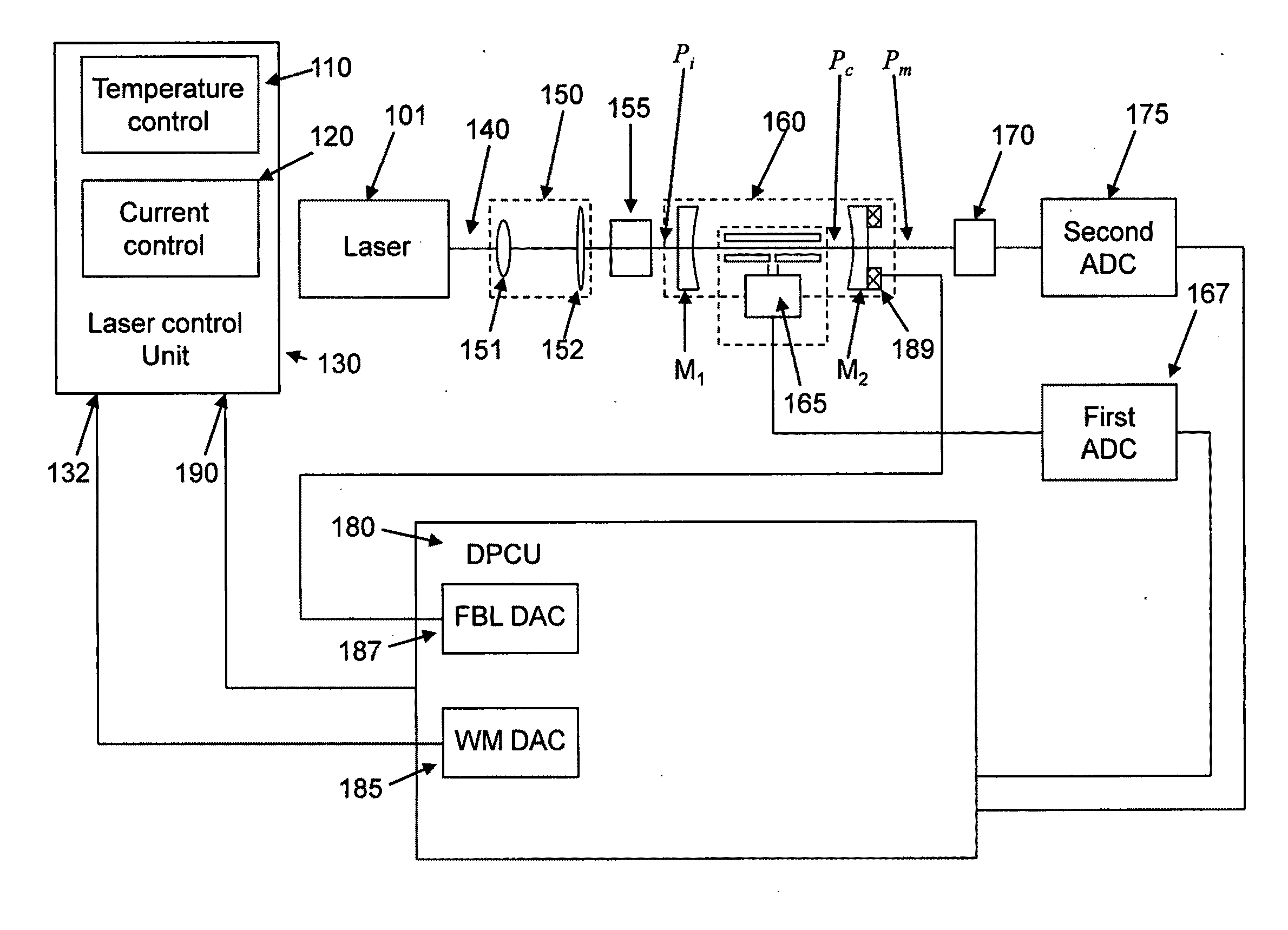
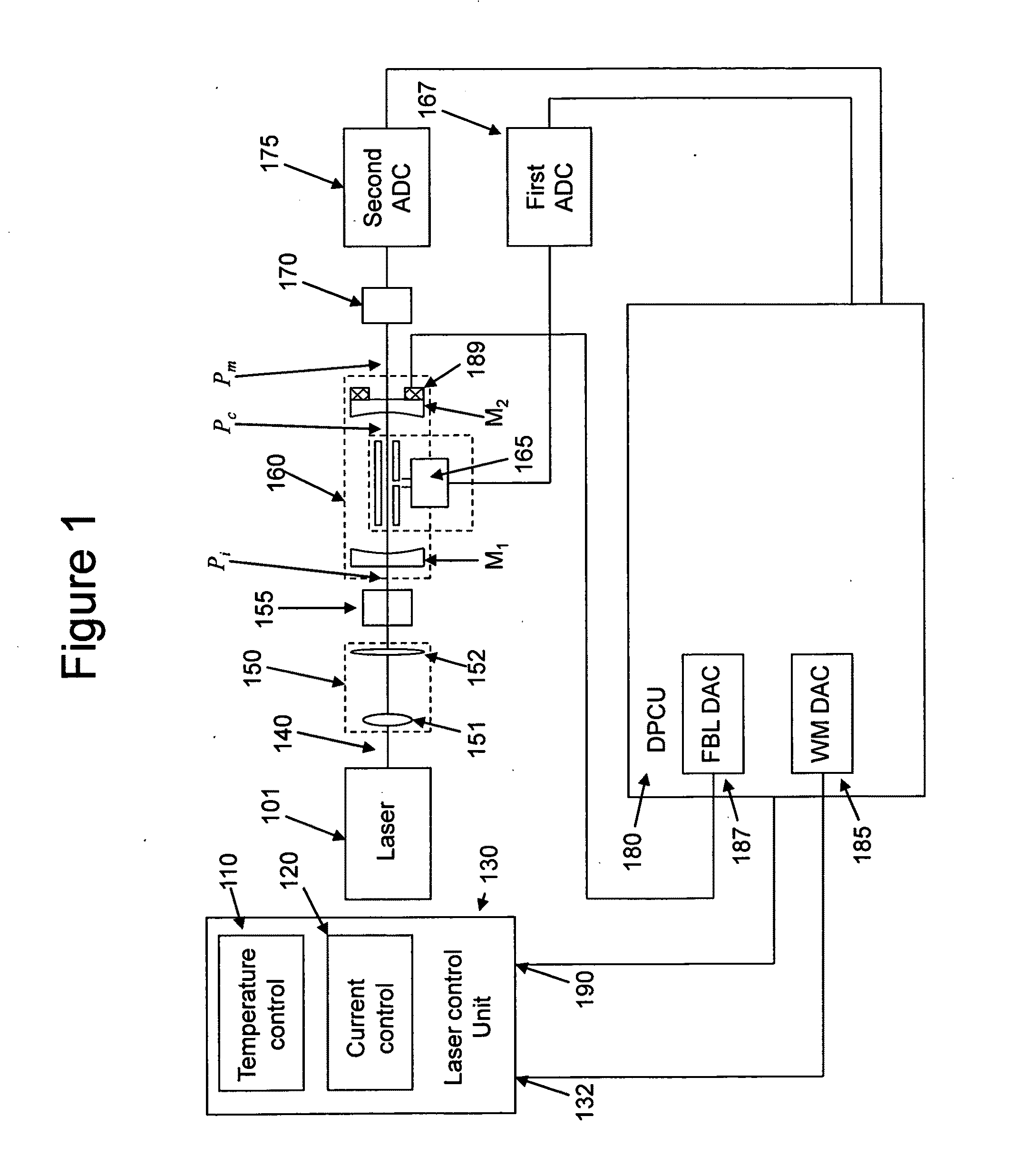
[0042]A schematic diagram of the gas detection system of the present invention is shown in FIG. 1. The present invention in a preferred embodiment contains a semiconductor laser source 101, preferably a distributed feedback (DFB) laser emitting a single emission line that can be tuned in the vicinity of the absorption line of the analyte species of interest within a range of several wave numbers. The operating wavelength of the laser can be changed or modulated, for example, by changing the operating temperature of the semiconductor laser chip, and / or its drive current. This is accomplished by electronic modules known in the art such as a diode laser temperature controller 110 and / or a low noise diode laser current controller 120. In other embodiments the laser can be of other known type subject to the requirement that its wavelength of operati...