Vibration Monitoring of a Magnetic Element in an Electrical Machine

a technology of vibration monitoring and magnetic elements, applied in the direction of motor/generator/converter stopper, dynamo-electric converter control, instruments, etc., can solve the problems of high thermocycle, high magnetic force on magnetic wedges, and magnetic wedges that can be easily displaced or even taken out of slots, so as to improve efficiency and reduce the core loss of electrical machines

Inactive Publication Date: 2011-09-08
SIEMENS AG
View PDF13 Cites 5 Cited by
  • Summary
  • Abstract
  • Description
  • Claims
  • Application Information

AI Technical Summary

Benefits of technology

[0012]According to a further embodiment, the one of the moving elements, to which the magnetic element is attached, comprises a winding and the magnetic element is positioned between the winding and the air gap, thereby forming a wedge in one embodiment. Such a configuration may result in an improved efficiency, for example in reduced core losses of the electrical machine.

Problems solved by technology

However, the magnetic wedges are subject to high magnetic forces and high thermocycles.
As a result, a magnetic wedge can get loose and hence can be displaced or even taken out of the slot.
As a result, the winding insulation is not protected any more, gets worn with time and finally could result in a short circuit.
Such a short circuit may generate high pulsating torques that may damage parts of the machine.

Method used


Image

  • Vibration Monitoring of a Magnetic Element in an Electrical Machine
  • Vibration Monitoring of a Magnetic Element in an Electrical Machine
  • Vibration Monitoring of a Magnetic Element in an Electrical Machine

Examples


Embodiment Construction

[0029]The illustration in the drawings is schematic. It is noted that in different figures, similar or identical elements are provided with the same reference signs or with reference signs which are different from the corresponding reference signs only within the first digit or an appended character.

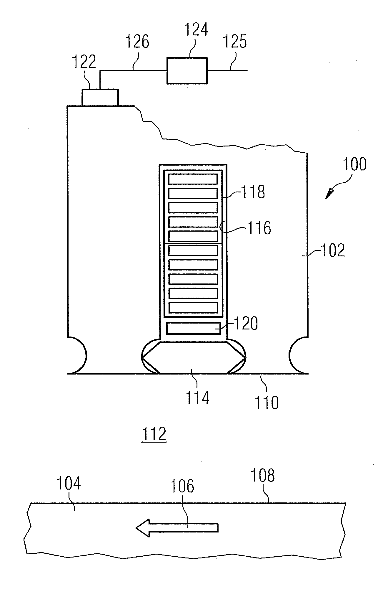
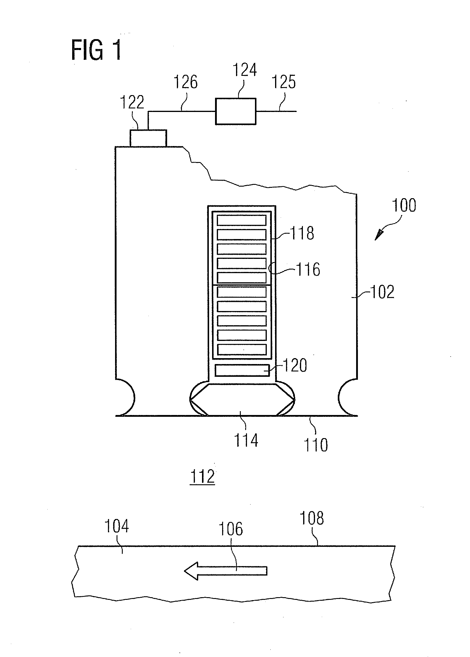
[0030]FIG. 1 shows in part a cross-sectional view of an electrical machine 100 in accordance with embodiments of the herein disclosed subject matter. The electrical machine 100 comprises two moving elements, a first moving element 102 in the form of a stator and a second moving element 104 in the form of a rotor. The rotor 104 is movable with respect to the stator 102, as indicated by arrow 106. It should be noted that although the rotor is depicted as having a flat surface 108, this is just for ease of illustration. Usually, when seen as a whole, the rotor 104 has a curved or generally circular surface 108. Likewise, also the stator 102 as a curved inner surface 110 which is also depict...


PUM


Abstract

An electrical machine is described including two moving elements, of which a first moving element is a stator of the electrical machine and the other moving element is a rotor of the electrical machine. Attached to one of the moving elements is a magnetic element which interacts with a magnetic flux in the electrical machine during operation. Further, a sensor is provided for measuring a vibrational quantity of the electrical machine and a control unit is configured for detecting a displacement of the magnetic element on the basis of the measured vibrational quantity. The electrical machine may be a generator or a motor.

Description

FIELD OF THE INVENTION[0001]The present invention relates to the field of electrical machines such as generators or motors.ART BACKGROUND[0002]In some electrical machines, a winding thereof is received in a core slot and an opening of the core slot is closed with a so-called wedge. The wedge may be magnetic or non-magnetic. A magnetic wedge has a certain magnetic property which is designed to provide an intended function. For example, respectively configured magnetic wedges are used to reduce core losses, vibrations, zigzag torque and magnetization current. Magnetic wedges are in particular used in induction machines.[0003]However, the magnetic wedges are subject to high magnetic forces and high thermocycles. As a result, a magnetic wedge can get loose and hence can be displaced or even taken out of the slot. As a result, the winding insulation is not protected any more, gets worn with time and finally could result in a short circuit. Such a short circuit may generate high pulsating...

Claims


Application Information

Patent Timeline
Patent Type & Authority Applications(United States)
IPC IPC(8): H02P29/00H02K11/00
CPCG01H1/003H02K11/001H02K3/493G01M7/00H02K11/20
Inventor ANDERSEN, KURTBESNERAIS, JEAN LEMOELGAARD, ANDERS
Owner SIEMENS AG
Why Eureka
Try Eureka