Rapidly quenched fe-based soft-magnetic alloy ribbon and its production method and core

a soft-magnetic alloy and fast technology, applied in the field of cores, can solve the problems of large core loss of fe-based amorphous alloys, low productivity of laser scribing methods, and increased core loss, and achieve the effect of reducing core loss

Active Publication Date: 2017-06-22
HITACHI METALS LTD
View PDF3 Cites 3 Cited by
  • Summary
  • Abstract
  • Description
  • Claims
  • Application Information

AI Technical Summary

Benefits of technology

[0011]Accordingly, an object of the present invention is to provide a quenched, Fe-based soft-magnetic alloy ribbon with reduced core loss, a core formed thereby, and a method for producing such quenched, Fe-based soft-magnetic alloy ribbon.SUMMARY OF THE INVENTION
[0013]As a result, the inventors have found that when an alloy melt is ejected onto a rotating cooling roll, (a) while keeping a transverse temperature distribution in a melt nozzle within ±15° C. to provide a melt paddle with as small a temperature distribution as possible, and (b) while grinding a cooling roll surface by a wire brush to form fine linear scratches having an average roughness Ra of 0.1-1 μm and a maximum roughness depth Rmax of 0.5-10 μm, a quenched, Fe-based soft-magnetic alloy ribbon having wave-like undulations on a free surface is formed, transverse troughs in the wave-like undulations having reduced meandering. The present invention has been completed based on such findings.

Problems solved by technology

Silicon steel is inexpensive and has a high magnetic flux density, but it suffers larger core loss than the Fe-based amorphous alloys.
This increased loss is called anomalous eddy current loss or excess loss, which is generated mainly by uneven magnetization change due to large magnetic domain widths of the alloy.
However, the laser scribing method has low productivity because of a small amount of treatments per a unit area.
Troughs reduce eddy current loss by the division of magnetic domains, but the meandering of transverse troughs increases hysteresis loss.
Increased hysteresis loss is serious particularly in wide amorphous alloy ribbons.
However, amorphous alloy ribbons obtained by the method described in JP 2002-316243 A have large core loss despite wave-like undulations on free surfaces.

Method used


Image

  • Rapidly quenched fe-based soft-magnetic alloy ribbon and its production method and core
  • Rapidly quenched fe-based soft-magnetic alloy ribbon and its production method and core
  • Rapidly quenched fe-based soft-magnetic alloy ribbon and its production method and core

Examples


example 1

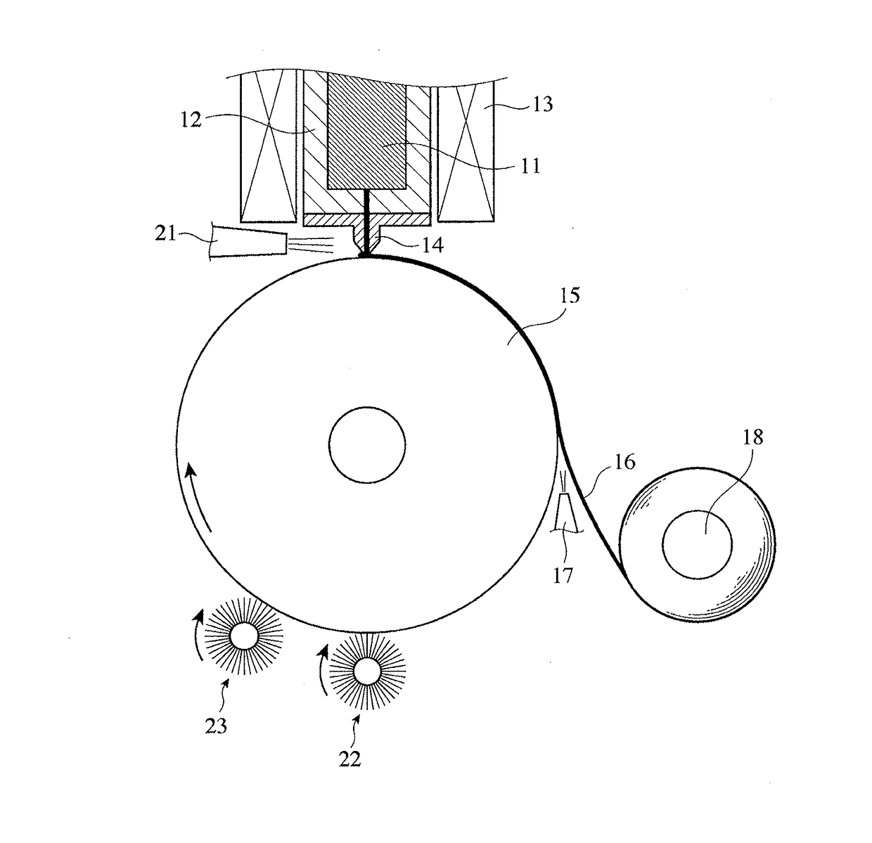
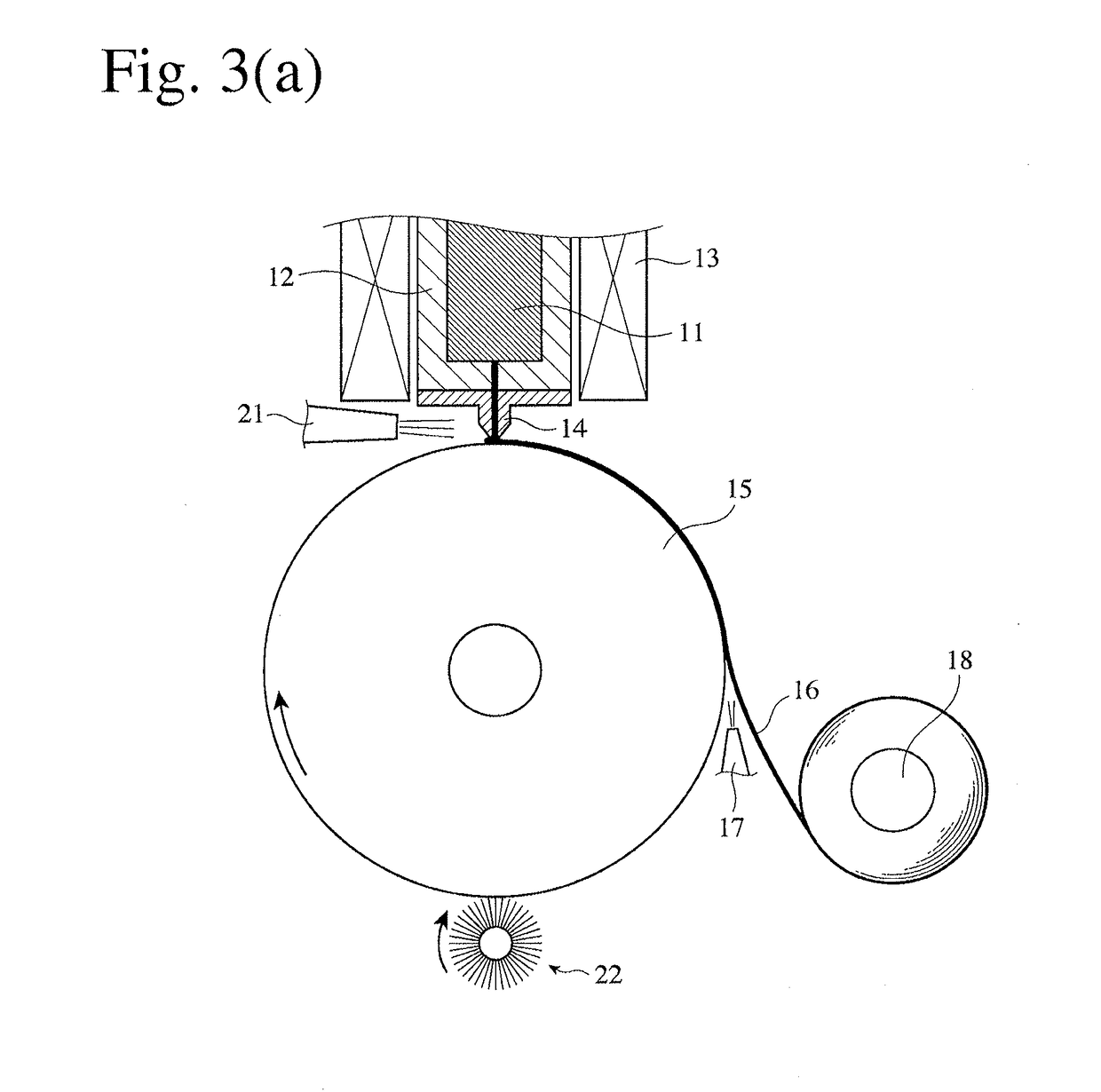
[0057]In the apparatus shown in FIG. 3(a), a ceramic-made nozzle 14 having a slit-shaped opening of 50 mm in length and 0.6 mm in width was used, with the gap between a tip end of the melt nozzle 14 and a cooling roll 15 being 250 μm. The water-cooling roll 15 made of a Cu—Cr—Zr alloy was rotated at a peripheral speed of 25.5 m / s. While ejecting a carbon dioxide gas at 1250° C. from a heating nozzle 21, an alloy melt at 1300° C., which comprised 11.5 atomic % of B, 9.5 atomic % of Si and 0.3 atomic % of C, the balance being substantially Fe and inevitable impurities, was ejected from the melt nozzle 14 onto the rotating water-cooling roll 15, to produce an Fe-based amorphous alloy ribbon of 50 mm in width and 24.3 μm in average thickness. During the production of the Fe-based amorphous alloy ribbon, the transverse temperature distribution of the melt nozzle 14 was 1200° C.±10° C., extremely uniform.

[0058]During the production of the Fe-based amorphous alloy ribbon, a wire brush roll...

examples 2-19

[0064]A ceramic-made nozzle 14 having a slit-shaped opening of 30 mm in length and 0.5-0.7 mm in width was used in the apparatus shown in FIG. 3(a), with a gap of 150-300 μm between a tip end of the nozzle 14 and a cooling roll 15. The water-cooling roll 15 made of a Cu—Be alloy was rotated at a peripheral speed of 20-35 m / s. While ejecting a carbon dioxide gas at 1190° C. from the heating nozzle 21, each alloy melt having the composition (atomic %) shown in Table 2 at 1250-1350° C. was ejected from the melt nozzle 14 onto the rotating water-cooling roll 15, to produce an Fe-based amorphous alloy ribbon of 30 mm in width. During the production of the Fe-based amorphous alloy ribbon, a transverse temperature distribution in the nozzle 14 was as extremely uniform as 1200° C.+10° C.

[0065]During the production of the Fe-based amorphous alloy ribbon, a wire brush roll 11 having stainless steel wires of 0.03 mm in diameter was rotated at a peripheral speed of 4 m / s in an opposite directio...

examples 20-39

[0071]A ceramic-made melt nozzle 14 having a slit-shaped opening of 30 mm in length and 0.5-0.7 mm in width was used in the apparatus shown in FIG. 3(a), with a gap of 150-300 μm between a tip end of the melt nozzle 14 and a cooling roll 15. The water-cooling roll 15 made of a Cu—Be alloy was rotated at a peripheral speed of 20-35 m / s. While ejecting a carbon dioxide gas at 1250° C. from a heating nozzle 21, each alloy melt having the composition (atomic %) shown in Table 4 at 1250-1350° C. was ejected from the melt nozzle 14 onto the rotating water-cooling roll 15, to produce an Fe-based amorphous alloy ribbon of 30 mm in width. During the production of each Fe-based amorphous alloy ribbon, a transverse temperature distribution in the melt nozzle 14 was as extremely uniform as 1200° C.±10° C.

[0072]During the production of each Fe-based amorphous alloy ribbon, a wire brush roll 11 having stainless steel wires of 0.04 mm in diameter was rotated at a peripheral speed of 4 m / s in an op...


PUM

PropertyMeasurementUnit
temperatureaaaaaaaaaa
roughness depth Rmaxaaaaaaaaaa

Abstract

A rapidly quenched Fe-based soft-magnetic alloy ribbon having wave-like undulations on a free surface, the wave-like undulations having transverse troughs arranged at substantially constant intervals in a longitudinal direction, and the troughs having an average amplitude D of 20 mm or less, is produced by a method comprising (a) keeping a transverse temperature distribution in a melt nozzle within ±15° C. to have as small a temperature distribution as possible in a melt paddle of the alloy, and (b) forming numerous fine linear scratches on a cooling roll surface by a wire brush, thereby providing a ground surface of the cooling roll with an arithmetical mean (average) roughness Ra of 0.1-1 μm and a maximum roughness depth Rmax of 0.5-10 μm.

Description

CROSS REFERENCE TO RELATED APPLICATIONS[0001]This application is a divisional of application Ser. No. 13 / 981,809 filed Jul. 25, 2013, which is a National Stage of International Application No. PCT / JP2012 / 051808 filed Jan. 27, 2012 (claiming priority based on Japanese Patent Application No. 2011-016017 filed Jan. 28, 2011), the contents of which are incorporated herein by reference in their entirety.FIELD OF THE INVENTION[0002]The present invention relates to a core having excellent magnetic properties for use in distribution transformers, reactors, choke coils, magnetic switches, etc., a quenched, Fe-based soft-magnetic alloy ribbon constituting such core, and its production method.BACKGROUND OF THE INVENTION[0003]As soft-magnetic materials used for cores for distribution transformers, etc., silicon steel, and ribbons of Fe-based amorphous alloys and Fe-based nanocrystalline alloys are known. Silicon steel is inexpensive and has a high magnetic flux density, but it suffers larger co...

Claims


Application Information

Patent Timeline
Patent Type & Authority Applications(United States)
IPC IPC(8): H01F41/02B22D11/06C21D1/62B22D11/00C22C45/02C21D9/573
CPCH01F41/0226C22C45/02C21D9/5737C21D1/62C21D2201/03B22D11/0611B22D11/0642B22D11/0682B22D11/001B22D11/0614B22D11/0668B22D11/0697B24B5/37C22C38/00H01F1/15333H01F27/25H01F3/04H01F41/022
Inventor YOSHIZAWA, YOSHIHITOOHTA, MOTOKIITO, NAOKI
Owner HITACHI METALS LTD
Why Eureka
Try Eureka