Motor having cores structure wherein magnetic circuit is designed in three dimensional configuration

a technology of three-dimensional configuration and motor, applied in the field of new motors, can solve the problems of increasing current value, increasing core temperature, deteriorating motor efficiency, etc., and achieve the effect of improving overall motor efficiency, improving overall magnetic permeability, and improving overall motor efficiency

Inactive Publication Date: 2006-06-01
ENOMOTO YUJI +5
View PDF13 Cites 13 Cited by
  • Summary
  • Abstract
  • Description
  • Claims
  • Application Information

AI Technical Summary

Benefits of technology

[0031] For the three dimensional magnetic circuit of the stepping motor or the like, it is possible to use a powdered iron core and sintered metal core to form the core back portion, while the silicon steel plate forming the tee tip and coil is kept unchanged. This can improve overall magnetic permeability, hence motor performances. According to this production method, the tee portion manufactured by the punched laminated layer of the silicon steel plate is set inside the sintered core molding die, and the

Problems solved by technology

This causes the eddy current with respect to the magnetic flux on the two-dimensional plane to occur on the plane perpendicular to the two-dimensional plane, with the result that the motor efficiency is deteriorated and core temperature is raised.
This results in an increased current val

Method used


Image

  • Motor having cores structure wherein magnetic circuit is designed in three dimensional configuration
  • Motor having cores structure wherein magnetic circuit is designed in three dimensional configuration
  • Motor having cores structure wherein magnetic circuit is designed in three dimensional configuration

Examples


embodiment 1

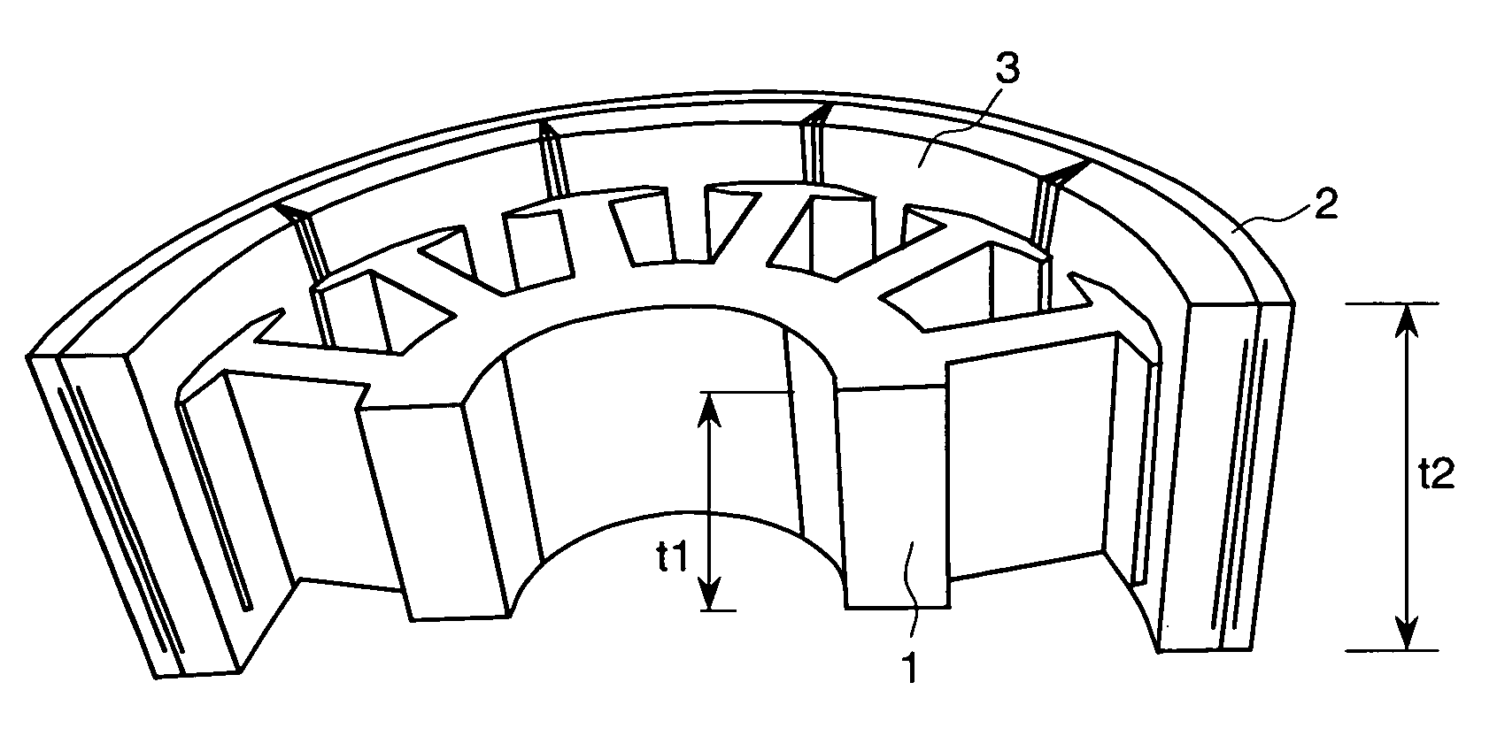
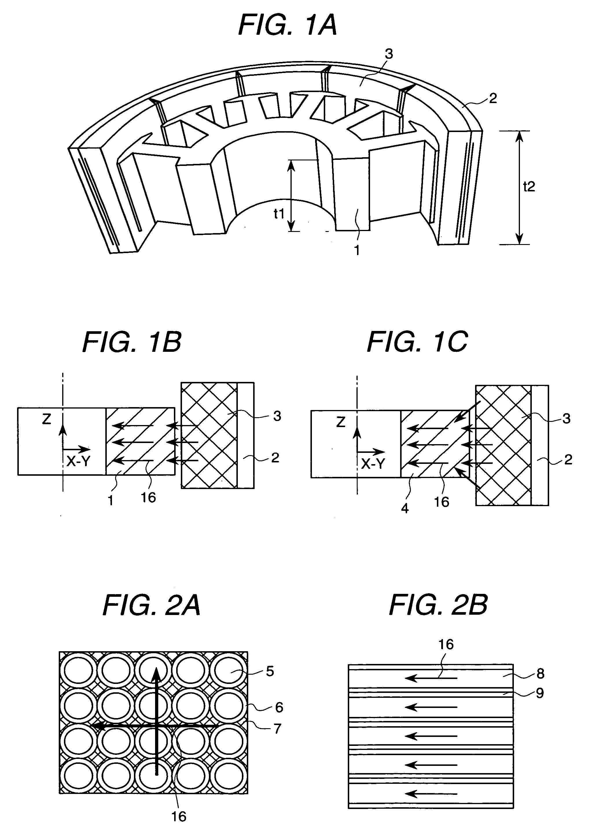
[0055]FIGS. 1A to 1C are examples of the epicycloidal motor magnetic motor according to the present invention. FIG. 1A is a partial perspective view of this motor. It shows the structure of a stator core constituting the portion where the magnetic flux vector changes its direction to the space other than the same plane in the magnetic circuit. In the present embodiment, the length (t2) of the rotor magnet 3 in the axial direction is set at 25 mm, while the laminate thickness (t1) of the stator core 1 in the axial direction is set to 15 mm.

[0056]FIG. 1B is a cross sectional view representing the prior art motor where silicon steel plates are laminated, and the flow of magnetic flux. In this case, the magnetic flux from the rotor magnet 3 enters the stator core 1 perpendicular to the X-Y plane. So in this two-dimensional plane, magnetic flux flows only to the same area as that of the X-Y plane of the stator core 1.

[0057]FIG. 1C is a cross sectional view representing the case where t...

embodiment 2

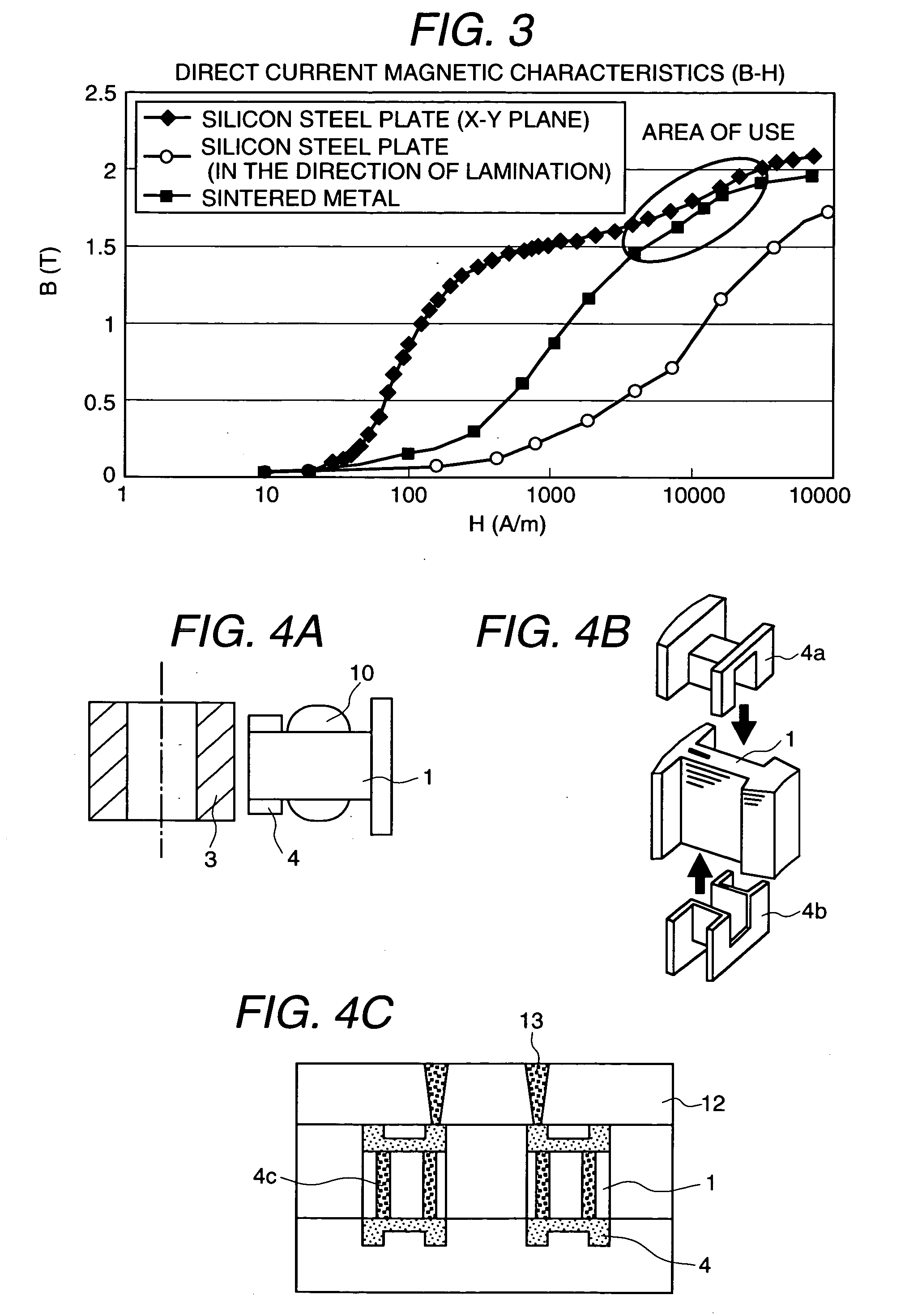
[0061]FIGS. 4A to 4C are drawings representing an example of a motor in FIGS. 1A to 1C where a hypocycloidal magnet is used. FIG. 4A is a cross sectional view. FIG. 4B is a perspective view showing the assembling procedure. FIG. 4C is a cross sectional view representing the integral formation by injection molding. In the present embodiment, the example shows the case where only the end of the stator core 1 is made of a sintered metal. It shows that the main magnetic flux flowing between the stator core 1 and rotor magnet 3 changes in three-dimensional direction through the sintered metal 4. Further, the silicon steel plate is placed at the center effectively utilizing the characteristics of the silicon steel plate in the X-Y direction. Only a part of the powdered iron core or sintered metal at the tip is supplemented by powdered iron core or sintered metal. The magnetic flux from the rotor magnet 3 provides the flow of a straight magnetic flux leading to the silicon steel plate and ...

embodiment 3

[0064]FIG. 5A is a drawing representing an example of using a powdered iron core or sintered metal in the structure of the hybrid (HB) type stepping motor. FIG. 5A is a perspective view, and FIG. 5B is its cross sectional view. FIG. 5C is a drawing representing the magnetic flux vector of the stator showing how the magnetic flux flows. The flow of the magnetic flux of the HOB type stepping motor can be described as follows: Magnetomotive force is provided by the magnet inserted into the rotor, and the magnetic flux emitted from the N pole enters the stator through the portion where the stator core 1 is meshed with the pinion of the rotor (the first pole for (a)), and returns to the position where the stator on the N pole side is meshed with the pinion of the rotor (the third pole for (a)) after passing through the stator. The main magnetic flux flowing between the stator core 1 and rotor magnet 3 changes in the three dimensional direction.

[0065] In the present embodiment as shown i...


PUM


Abstract

In order to provide a motor characterized by a high level of efficiency equal to or better than that of using the silicon steel plate, achieved by easy production method and reduced core loss, which result from reduction in the manpower for production by using the sintered metal or powdered iron core in at least one of the stator and rotor, the present invention provides a motor comprising a stator and a rotor wherein either one of said stator or rotor has a magnet, and the other has a magnetic substance. This motor is further characterized in that the main magnetic flux flowing between the stator and rotor changes in the three-dimensional directions according to the magnetic structure of this motor, and at least part of said magnetic substance is composed of an aggregate of magnetic powder.

Description

BACKGROUND OF THE INVENTION [0001] 1. Field of the Invention [0002] The present invention relates to a new motor having core structure of a stator or a rotor wherein the magnetic circuit is designed in a three dimensional configuration, for example, in a stepping motor, linear motor, brush-less motor and axial gap motor. [0003] 2. Prior Art [0004] [Patent Literature 1] Japanese Application Patent Laid-open Publication No. Hei 05-308768 [0005] [Patent Literature 2] Japanese Application Patent Laid-open Publication No. Hei 08-242572 [0006] [Patent Literature 3] Japanese Application Patent Laid-open Publication No. Hei 09-56139 [0007] [Patent Literature 4] Japanese Application Patent Laid-open Publication No. Hei 09-65638 [0008] [Patent Literature 5] Japanese Application Patent Laid-open Publication No. Hei 09-182329 [0009] [Patent Literature 6] Japanese Application Patent Laid-open Publication No. Hei 09-233737 [0010] [Patent Literature 7] Japanese Application Patent Laid-open Publica...

Claims


Application Information

Patent Timeline
IPC IPC(8): H02K41/00H02K15/12H02K21/12H02K1/02H02K1/27H02K37/04H02K41/03
CPCH02K1/02H02K1/08H02K15/022H02K41/03
Inventor ENOMOTO, YUJIHINO, NORIAKIKAWAMATA, SHOUICHIIDE, KAZUMASAMATSUDA, YASUOSAKAI, TOSHIHIKO
Owner ENOMOTO YUJI
Why Eureka
Try Eureka