Surface-treated reduced iron powder and method for manufacturing the same, and powder magnetic core

Inactive Publication Date: 2011-05-05
TDK CORPARATION
View PDF4 Cites 6 Cited by
  • Summary
  • Abstract
  • Description
  • Claims
  • Application Information

AI Technical Summary

Benefits of technology

[0040]The invention provides: a powder magnetic core that exhibits sufficiently reduced core loss in the range of high frequencies as well as low frequencies and is applicable to high frequencies of 1 MHz or higher; surface-treated reduced iron powder that allows such a po

Problems solved by technology

However, when the inventors of the present invention produced a powder magnetic core using reduced iron powder obtained according to the method described in Patent Document 1, the produced powder magnetic core had a problem of exhibiting large core loss, in particular, exhibiting extremely large core loss when driven at a high frequency of 1 MHz or more.
The methods disclosed in Patent Documents 2 and 3 also enable the stable production of reduced iron powder having a primary particle average diameter of several micrometers down to the submicron range; however, as with Patent Document 1 above, there are problems in that when producing a powder magnetic core from such reduced iron powder, the powder magnetic core exhibits large core loss, and in particular, exhibits extremely large core loss when driven at a high frequency of 1 MHz or more.
As stated above, although reduced iron powder obtained, for example, by reducing iron oxide is fine iron powder and has been expected to be applied to powder magnetic cores, a technique that sufficiently allows such application has not yet been found.
However, according to the knowledge of the inventors of the invention, it seems that, in the above-mentioned conventional techniques, it is actually impossible to reduce eddy current loss to a sufficient level for reasons such as: magnetite having low electric resistivity and not having sufficient insulating properties, and thus making it difficult to reduce eddy current loss to a sufficiently small value; an insulating resin layer not being easily formed on t

Method used


Image

  • Surface-treated reduced iron powder and method for manufacturing the same, and powder magnetic core
  • Surface-treated reduced iron powder and method for manufacturing the same, and powder magnetic core
  • Surface-treated reduced iron powder and method for manufacturing the same, and powder magnetic core

Examples


example 1

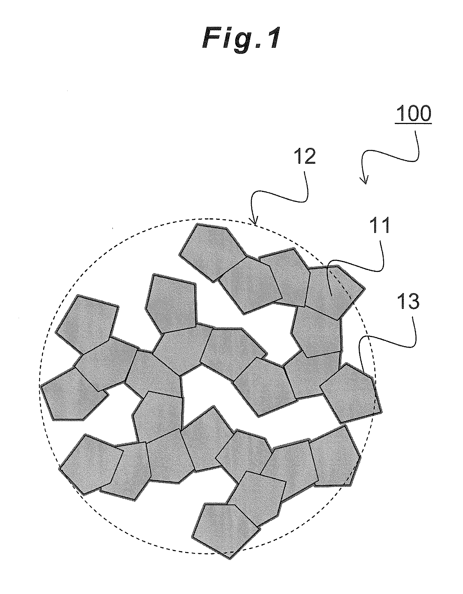
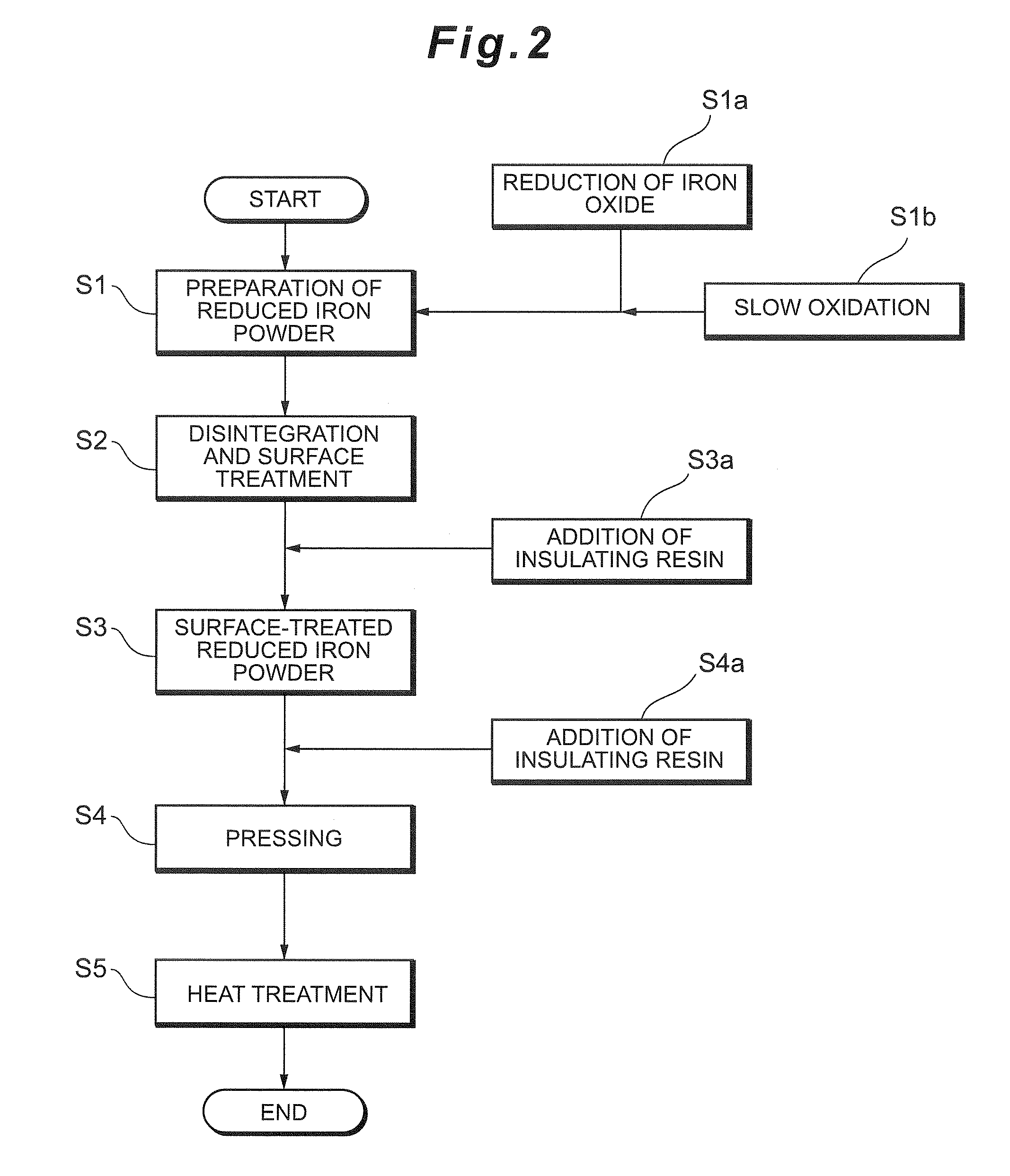
[0097]5 g of the reduced iron powder of Comparative Example 1 was charged in a 250 ml polyethylene bottle, to which 50 g of steel balls (Φ3.2 mm, 0.16 μg / pc) and 20 g of acetone (reagent, 99%) were added, and phosphoric acid (reagent, 89%) was further added so that the phosphoric acid was 1.00% by weight relative to the weight of the reduced iron powder. After that, disintegration treatment and surface treatment were carried out for 6 hours using a uniaxial ball mill. The reduced iron powder after the disintegration treatment and surface treatment was taken out, separated from the steel balls with a 2 mm mesh sieve, and heated to evaporate acetone and dried, thereby obtaining (disintegrated / surface-treated) reduced iron powder of Example 1. When observing the reduced iron powder of Example 1 with SEM, the primary particle diameter was in the range of 200-300 nm.

[0098]In the same manner as Comparative Example 1 other than using the obtained reduced iron powder of Example 1, a powder ...

example 2

[0099]In the same manner as Example 1 other than adding phosphoric acid to be 1.50% by weight relative to the weight of the reduced iron powder, (disintegrated / surface-treated) reduced iron powder of Example 2 and a powder magnetic core of Example 2 were obtained.

example 3

[0100]In the same manner as Example 1 other than adding phosphoric acid to be 2.00% by weight relative to the weight of the reduced iron powder, (disintegrated / surface-treated) reduced iron powder of Example 3 and a powder magnetic core of Example 3 were obtained.

[0101]Table 1 shows the evaluation of the properties of the powder magnetic cores of Examples 1-3 and Comparative Examples 1-2.

TABLE 1Surface-treatedReduced IronPowderSecondaryParticleTreatment of Reduced Iron PowderPrimaryD90%Surface TreatmentParticleParticleReduction of IronDisintegrationAddedDiameterDiameterOxideYes / NoYes / NoAgentAmount[nm][μm]Comp. Ex. 1600° C. × 5 h, followedNoNo——100-500150by slow oxidationComp. Ex. 2600° C. × 5 h, followedYesNo——100-5006by slow oxidationEx. 1600° C. × 5 h, followedYesYesPhosphoric1.00 wt %100-5006by slow oxidationacidEx. 2600° C. × 5 h, followedYesYesPhosphoric1.50 wt %100-5006by slow oxidationacidEx. 3600° C. × 5 h, followedYesYesPhosphoric2.00 wt %100-5006by slow oxidationacidSurfac...


PUM

PropertyMeasurementUnit
Weightaaaaaaaaaa
Lengthaaaaaaaaaa
Fractionaaaaaaaaaa

Abstract

The invention provides surface-treated reduced iron powder from which a powder magnetic core can be produced so that the powder magnetic core has small core loss and small frequency-dependence of the core loss and exhibits small core loss even when driven at high frequencies of 1 MHz or more. The surface-treated reduced iron powder is obtained by at least surface-treating reduced iron powder prepared by a reduction and slow oxidation method, and contains secondary particles formed through agglomeration of primary particles, the primary particles having an average particle diameter of 0.01-5 μm. The secondary particles have a D90% particle diameter of 20 μm or less, the surface of the primary particles is at least in part coated with an insulating layer containing iron phosphate, and the phosphorus content is 500-10000 ppm.

Description

CROSS-REFERENCES TO RELATED APPLICATIONS[0001]The present application relates to and claims priority from Japanese Patent Application No. 2009-250708, filed on Oct. 30, 2009, the entire disclosure of which is incorporated herein by reference.BACKGROUND[0002]1. Field of the Invention[0003]The present invention relates to surface-treated reduced iron powder and a method for manufacturing the same, and a powder magnetic core.[0004]2. Description of Related Art[0005]Powder magnetic cores have been widely used for magnetic cores provided in inductors, etc. The properties required for powder magnetic cores are high electric resistance and small core loss (magnetic core loss), and in order to obtain powder magnetic cores having such properties, various attempts have been made, for example, using, as the powder magnetic core material, magnetic metal powder such as alloy powder of FeSi-type, FeNi-type, etc., produced by an atomizing method and pure iron powder (high-purity iron powder) produ...

Claims


Application Information

Patent Timeline
IPC IPC(8): H01F1/06H01F1/26B22F1/142B22F1/145B22F1/148B22F1/16
CPCB22F1/0085B22F1/0088B22F1/0096H01F41/0246H01F1/24H01F1/26H01F3/08B22F1/02B22F1/148B22F1/142B22F1/145B22F1/16
Inventor KURODA, TOMOFUMIKOEDA, MASAHITO
Owner TDK CORPARATION
Why Eureka
Try Eureka