Cutting device and printer

Inactive Publication Date: 2007-08-02
SEIKO INSTR INC
View PDF7 Cites 8 Cited by
  • Summary
  • Abstract
  • Description
  • Claims
  • Application Information

AI Technical Summary

Benefits of technology

[0008]With this construction, at the start of cutting which is considered to be a time when the blades meet with the highest resistance, the portions of the cutting edge each forming a larger angle with respect to the cut surface cut into the object to be cut at an acute angle, thereby making it possible to smoothly start cutting. Further, after the smooth cutting is performed to a certain extent, the central portion of the object to be recorded is cut by the portions of the cutting edge each forming a smaller angle with respect to the cut surface, thereby preventing significant elongation of cutting time and significant increase in size of the movable blade and the stroke thereof. Thus, it is possible to suppress increase in size of the cutting device as a whole.
[0011]A printer according to the present invention is characterized by including a recording device for effecting recording on the recording medium and a cutting device having one of the above-mentioned structures in which the recording medium on which recording is effected by the recording device is cut as an object to be cut. According to the printer, it is possible to cut the continuous paper to a predetermined length to continuously produce the cut sheets with ease each of which has undergone desired recording.
[0012]According to the present invention, at a start of cutting when resistance to cutting is at the maximum level, a cutting edge having portions each forming a larger angle with respect to a cut surface is used, thereby making it possible to reduce the resistance as compared to the prior art. Accordingly, even a thick and hard object to be cut can be cut relatively smoothly. Further, in a latter half of a cutting process, in which the resistance to cutting is lower than that at the start of cutting, the cutting edge having portions each forming a smaller angle with respect to the cut surface is used, thereby making it possible to complete the cutting in a relatively short time. Further, it is not necessary to increase the movable blade and the stroke thereof in size, thereby making it possible to suppress increase in size of the cutting device as a whole.

Problems solved by technology

Therefore, working efficiency of the cutting device is high, but resistance at a time of cutting is high, so there are some cases where the paper cannot be smoothly cut.
In this case, there may arise a problem in that the sheet material is not cut but bent.

Method used


Image

  • Cutting device and printer
  • Cutting device and printer
  • Cutting device and printer

Examples


Embodiment Construction

[0026]In the following, embodiments of the present invention will be described with reference to the drawings.

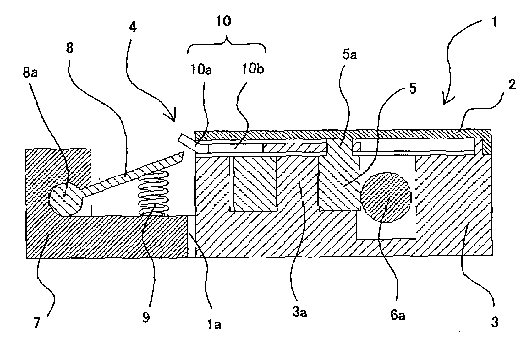
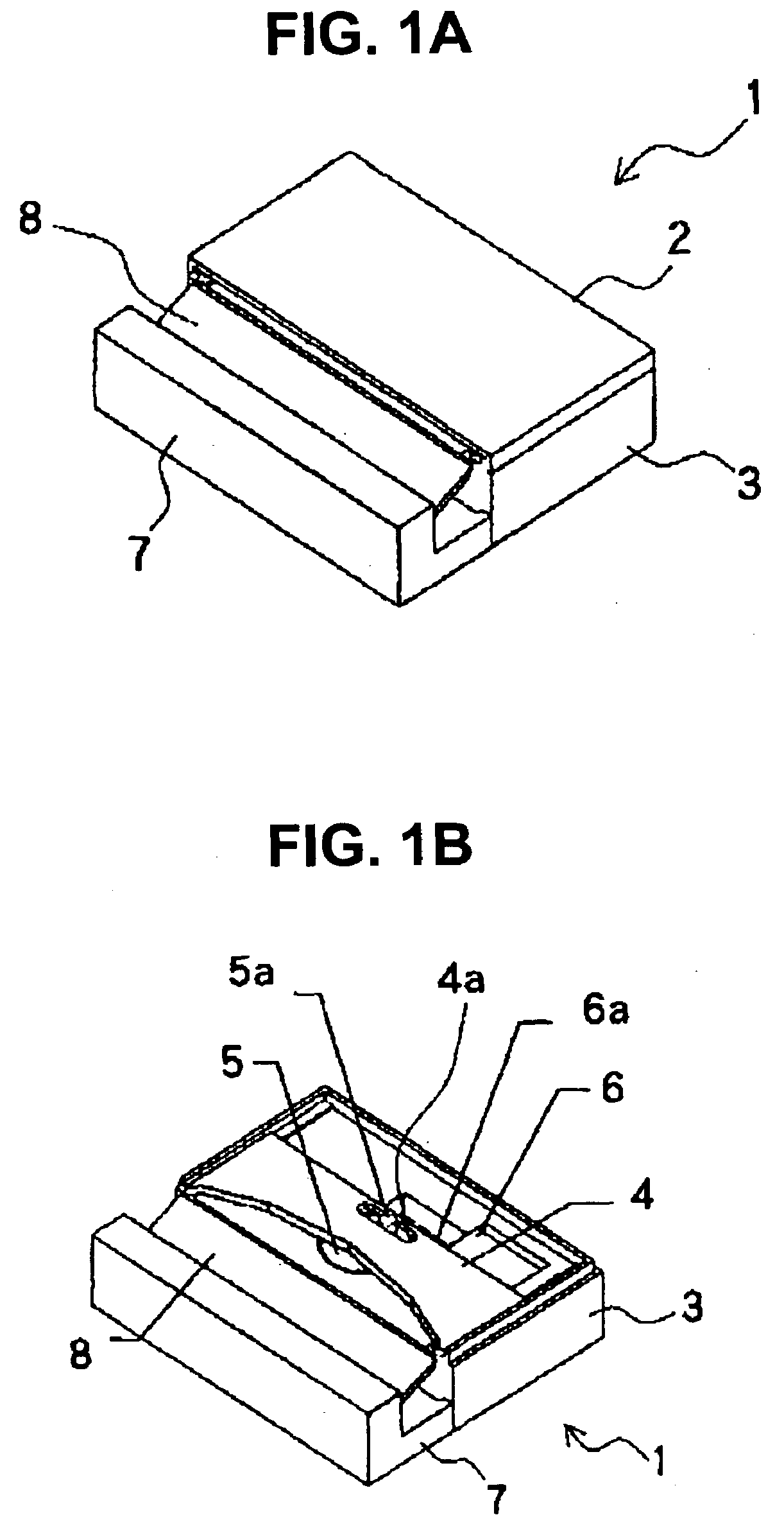
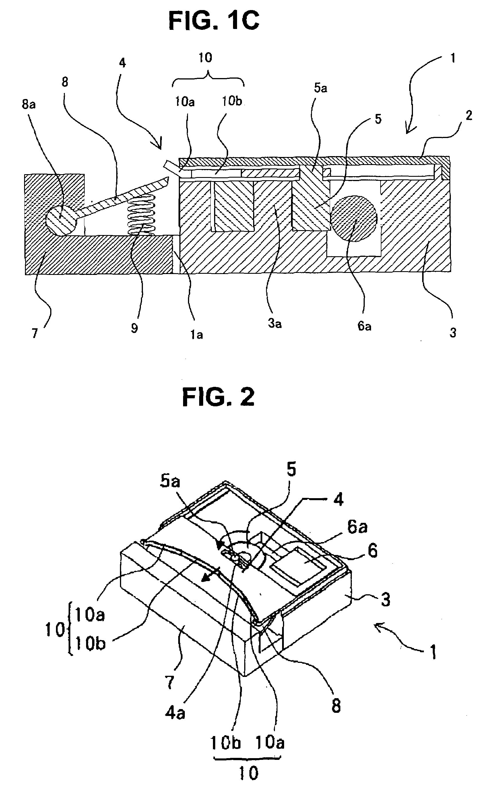
[0027]FIGS. 1 and 2 each show a cutting device 1 of the present invention. FIG. 1A is a perspective view of the cutting device 1, FIG. 1B is a perspective view of a state where an upper cover 2 of the cutting device 1 is removed, and FIG. 1C is a side sectional view of the cutting device 1. FIG. 2 is a perspective view showing a cutting operation of the cutting device 1 with the upper cover 2 thereof being removed.

[0028]In the cutting device 1, a casing 3 includes therein a movable blade 4, a drive gear 5, and a motor 6 which are covered with the upper cover 2. Further, a stationary blade 8 and a stationary blade pressing spring 9 are mounted on a frame 7 attached to the casing 3. A shaft 3a provided in the casing 3 is engaged with a central hole of the drive gear 5 such that the drive gear 5 is attached so as to be rotatable. The motor 6 arranged in the casing 3 has a drive...


PUM

PropertyMeasurementUnit
Angleaaaaaaaaaa

Abstract

A cutting device includes a movable blade and a stationary blade opposed to the movable blade across a sheet-like object to be cut. The movable blade is formed into a concave shape retracted inwardly from opposite end portions toward a central portion thereof. The stationary blade is formed into a straight line in parallel to the cut surface of the object. An angle of each of portions of the cutting edge on sides of the opposite end portions with respect to a cut surface of the object to be cut is larger than an angle of each of portions of the cutting edge on both sides of the central portion with respect to the cut surface.

Description

[0001]This application claims priority to Japanese Patent Application No. 2006-020296 filed Jan. 30, 2006, the entire content of which is hereby incorporated by reference.BACKGROUND OF THE INVENTION[0002]The present invention relates to a cutting device for cutting a sheet-like object to be cut, and to a printer having the cutting device.[0003]Conventionally, there has been proposed, for example, a printer including therein a recording device and a cutting device for effecting recording on a part of a long continuous paper and for producing a cut sheet having a predetermined length by cutting the part on which recording is effected. A typical cutting device includes a stationary blade and a movable blade and has a structure in which the movable blade is moved so that the movable blade and the stationary blade sandwich the continuous paper to cut the continuous paper. In such the cutting device, in a case where both a cutting edge of the movable blade and a cutting edge of the statio...

Claims


Application Information

Patent Timeline
IPC IPC(8): B26D1/08
CPCB26D1/0006B26D1/085B26D2001/0066B26D2001/006B26D3/12Y10T83/8778Y10T83/8854
Inventor ITO, AKIHIKO
Owner SEIKO INSTR INC
Why Eureka
Try Eureka