Charge control system

a charge control and control system technology, applied in the direction of electric vehicles, battery/fuel cell control arrangements, transportation and packaging, etc., can solve the problems of preventing enhancement of fuel efficiency, power generation control for power generation restraints being disabled, etc., to enhance fuel efficiency, enhance fuel efficiency, and effective use of idle stop functions

Active Publication Date: 2011-09-08
DENSO CORP
View PDF10 Cites 18 Cited by
  • Summary
  • Abstract
  • Description
  • Claims
  • Application Information

AI Technical Summary

Benefits of technology

[0011]As described above, the charge control system implements power generation control adaptive for a large load current to thereby simultaneously maintain the battery charge level (SOC) and enhance the fuel efficiency of the vehicle under practical use conditions. The ISS-enabled vehicle implements the power generation control taking into account the discharge amount during idle stop, which leads to effective use of the idle stop function. When the load current is low, the charge control can suppress an extra power generation amount, which also leads to enhancement of the fuel efficiency. Further, the charge control can maintain a low battery charge level such that the regenerative power generation doesn't occur, therefore a large margin can be reserved for the regenerative power generation, which leads to further enhancement of the fuel efficiency.

Problems solved by technology

However, a heavy electrical load, such as an air conditioner or a heater, should be taken into account under practical use conditions, where a battery charge / discharge integrated value is not balanced (or zeroed).
As a result of a resultant drop in battery charge level, the power generation control for the power generation restraint gets disabled.
As a result of such a further drop in battery charge level, both the idle stop function and the power generation control for the power generation restraint become disabled, which prevents enhancement of the fuel efficiency.

Method used


Image

  • Charge control system
  • Charge control system
  • Charge control system

Examples


Embodiment Construction

[0021]The present inventions will be described more fully hereinafter with reference to the accompanying drawings. Like numbers refer to like elements throughout.

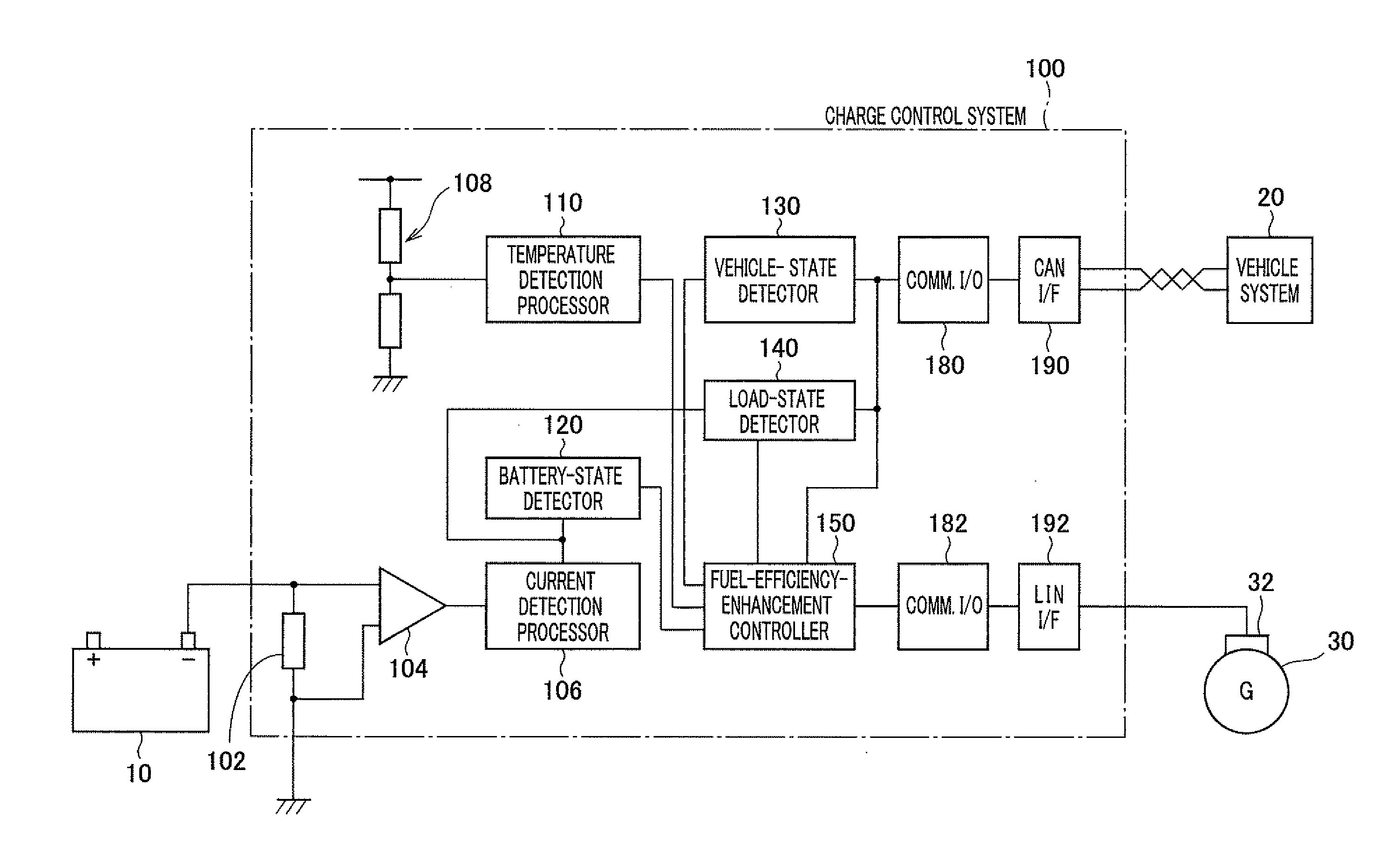
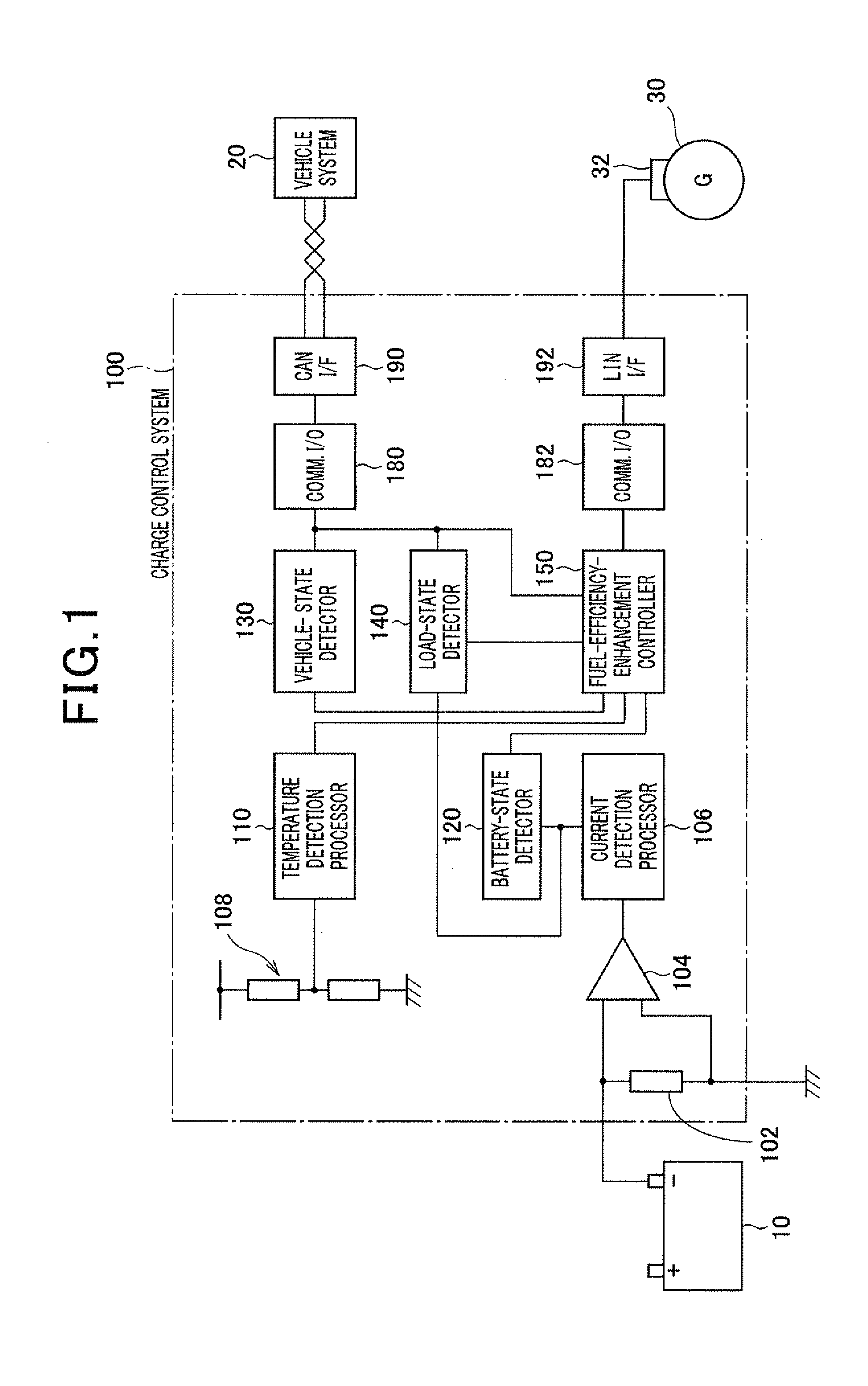
[0022]FIG. 1 is a schematic block diagram of a charge control system in accordance with one embodiment of the present invention. The charge control system 100, which may be mounted in a vehicle such as a passenger car or a truck or the like, includes a shunt resistor 102, a differential amplifier 104, a current detection processor 106, a temperature detector 108, a temperature detection processor 110, a battery-state detector 120, a vehicle-state detector 130, a load-state detector 140, a fuel-efficiency-enhancement controller 150, a communication input / output unit (communication I / O) 180, 182, a CAN interface (CAN I / F) 190, a LIN interface (LIN I / F) 192.

[0023]The CAN interface 190 receives data from or transmits data to the vehicle system 20 in accordance with a CAN protocol. Various signals, such as a fuel-cut (F / C) signa...


PUM


Abstract

An in-vehicle charge control system includes a vehicle-state detector that detects a running state of a vehicle, a battery-state detector that detects a charge level of an in-vehicle battery, a fuel-efficiency-enhancement controller that predicts a discharge amount to be discharged by the battery under a discharge condition, sets a lower limit of the battery charge level on the basis of the battery charge level detected by the detector such that the lower limit of the battery charge level is higher than a battery charge level at which the battery begins to degrade by the predicted discharge amount, and controls a power generation amount of a vehicle generator according to the vehicle state detected by the detector. The system with this configuration can maintain the battery charge level and enhance the fuel efficiency simultaneously under practical use conditions.

Description

CROSS-REFERENCE TO RELATED APPLICATION[0001]This application is based on and claims the benefit of priority from earlier Japanese Patent Application No. 2010-49712 filed Mar. 5, 2010, the description of which is incorporated herein by reference.BACKGROUND[0002]1. Technical Field of the Invention[0003]This invention relates to an in-vehicle charge control system that controls charging operations for an in-vehicle battery.[0004]2. Related Art[0005]Conventionally, as disclosed in Japanese Unexamined Patent Application Publication No. 2003-209935, there is known a charge control apparatus, which is composed of battery-state (voltage, current, and temperature) detection means, regulated-voltage control means (a microcomputer) and a regulator, controls a regulated voltage so that an integrated value of a discharging / charging current is zeroed. This apparatus is intended to prevent deterioration in fuel efficiency and battery liquid loss due to overcharge by controlling the regulated volta...

Claims


Application Information

Patent Timeline
Patent Type & Authority Applications(United States)
IPC IPC(8): H02J7/00
CPCH02J7/00H02J7/1446B60L58/13B60L58/15H02J7/1438
Inventor TAKAHASHI, SHINMAEDA, SHUNICHI
Owner DENSO CORP
Why Eureka
Try Eureka