Data transfer device and data transfer system

Inactive Publication Date: 2011-09-08
HITACHI LTD
View PDF2 Cites 2 Cited by
  • Summary
  • Abstract
  • Description
  • Claims
  • Application Information

AI Technical Summary

Benefits of technology

[0009]According to one aspect of this invention, it is possible to correct corrupt synchronization headers and to suppress loss of effective data or reduction of transfer efficiency due to discarding of blocks.

Problems solved by technology

Such a data error in the physical layer cannot be recovered by error correction in the upper layers (the data link layer, the network layer, and the like).
For example, if the synchronization header is corrupt and rewritten into “00” or “11” by the noise on a transmission path or the like, the receiver node cannot judge whether or not the payload is the user data or the data including a control code and therefore cannot decode received data, with the result that the 64-bit payload is discarded.

Method used


Image

  • Data transfer device and data transfer system
  • Data transfer device and data transfer system
  • Data transfer device and data transfer system

Examples


first embodiment

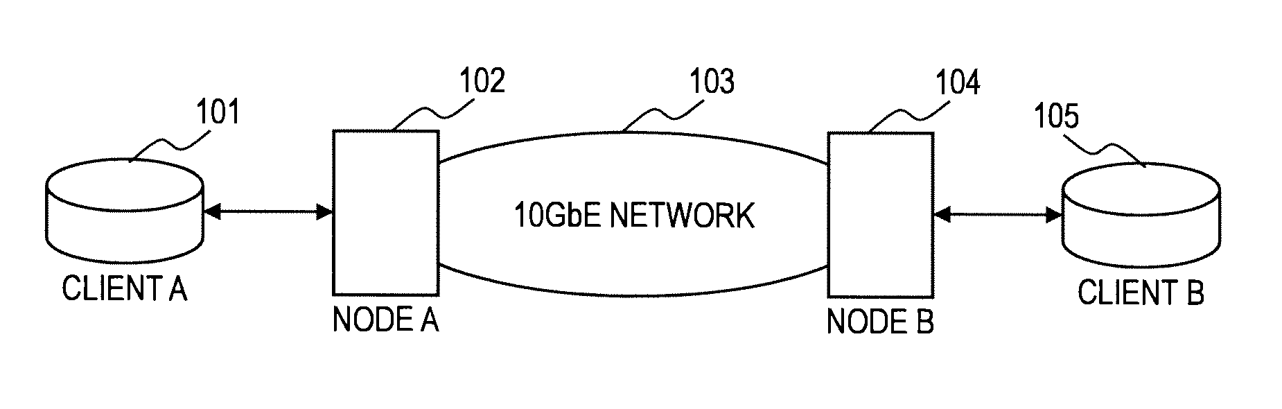
[0024]FIG. 1 is a diagram illustrating a configuration of a system according to a first embodiment of this invention.

[0025]The system of the first embodiment includes client terminals 101 and 105, network nodes 102 and 104, and a network 103.

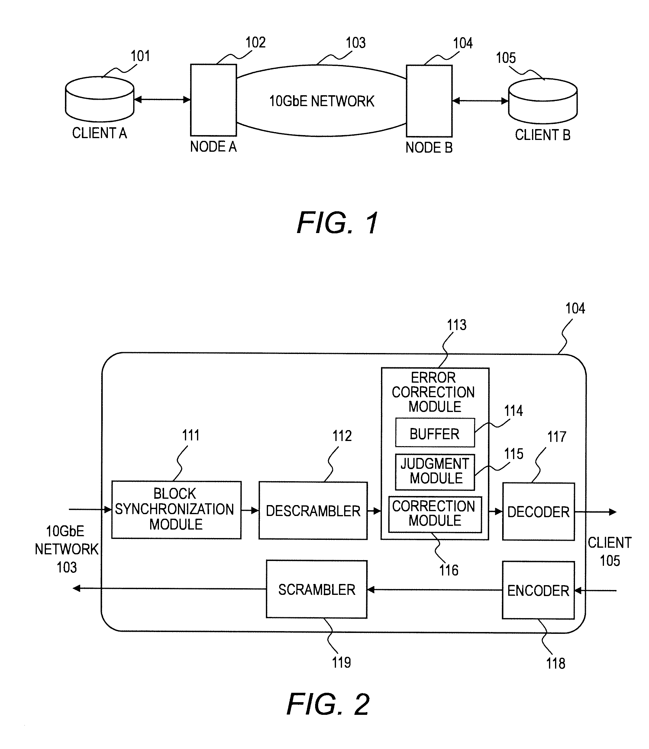
[0026]The client terminals 101 and 105 are each a computer that transmits / receives data via the network 103, including a processor, a memory, and a network interface. The network nodes 102 and 104 are each a data transfer device that transfers data between a client and another node and between nodes and are coupled to each other by the network 103. Details of a configuration of each of the network nodes 102 and 104 will be described later with reference to FIG. 2.

[0027]The network 103 uses a plurality of network nodes to transfer data to a specified destination address. It should be noted that the network 103 illustrated in FIG. 1 includes two network nodes 102 and 104, but may include more than two network nodes. The network 103 is a so-called ...

second embodiment

[0062]Next described is a second embodiment of this invention.

[0063]In the above-mentioned first embodiment, the synchronization headers of the preceding and succeeding blocks are used to correct the synchronization header of the intermediate block, while in the second embodiment, the synchronization headers and the block type fields of the preceding and succeeding blocks are used. Further, the block type field of the intermediate block may be used in an auxiliary manner.

[0064]Configuration of a system of the second embodiment and hardware configuration of network nodes of the second embodiment are the same as those of the above-mentioned first embodiment. In the second embodiment, the same components and the same processing steps as those of the above-mentioned first embodiment are denoted by the same reference numerals and symbols, and description thereof is omitted.

[0065]The network node of the second embodiment is different from the network node of the above-mentioned first embo...

modified example

[0101]In the error correction processing of the second embodiment, it can be judged whether or not the synchronization header of the intermediate block can be corrected not only by the logic illustrated in FIG. 7 but also by finding a specific combination from the synchronization headers and the block type fields of the preceding and succeeding blocks. Next, such a modified example is described.

[0102]FIG. 11 is a diagram illustrating an error correction table 200 according to the modified example of the second embodiment.

[0103]The error correction table 200 according to the modified example of the second embodiment includes a synchronization header 201 of the preceding block, a block type field 202 of the preceding block, a synchronization header 203 of the succeeding block, a block type field 204 of the succeeding block, a block type field 205 of the intermediate block, and a correction candidate 206 for the synchronization header. The error correction table 200 is stored in the me...


PUM


Abstract

A transfer device according to an embodiment transfers blocks generated by dividing a frame into pieces of data and adding a synchronization header each of the pieces of data. The blocks comprise a first, second and third blocks in this order. The transfer device is configured to acquire a first synchronization header in the first block, a second synchronization header in the second block and a third synchronization header in the third block, judge, in a case where a value of the second synchronization header is incorrect, as to whether or not the value of the second synchronization header can be estimated based on the first and the third synchronization headers so that the second block is consistent with the first and third blocks, and correct the second synchronization header into the estimated value.

Description

CLAIM OF PRIORITY[0001]The present application claims priority from a Japanese patent application JP 2010-46264 filed on Mar. 3, 2010, the content of which is hereby incorporated by reference into this application.FIELD OF THE INVENTION[0002]This invention relates to a data transfer device, and more particularly to a technology for recovering data (for example, synchronization header) used for transferring data in the physical layer.BACKGROUND OF THE INVENTION[0003]In some protocols used for data transfer performed between network nodes, the synchronization header (SyncHeader) for data synchronization is inserted at predetermined intervals. For example, in 10 Gigabit Ethernet, 64B / 66B encoding is used to transmit data in 66-bit blocks (see, for example, JP 2005-72714 A). The 66-bit block includes a 2-bit synchronization header (“01” or “10”) and a 64-bit payload. In other words, the 2-bit synchronization header is inserted every 66 bits.[0004]Hence, a sender node encodes 64-bit data...

Claims


Application Information

Patent Timeline
IPC IPC(8): H04J3/24
CPCH04L1/0072
Inventor NAKAJIMA, TETSUYASHIBASAKI, MASATOSHITAMURA, YUKIHISA
Owner HITACHI LTD
Why Eureka
Try Eureka